- Article
- Open access
- Published:
Retrofit Design of Damaged Prestressed Concrete Cylinder Pipes
International Journal of Concrete Structures and Materials volume 7, pages 265–271 (2013)
Abstract
Prestressed concrete cylindrical pipe (PCCP) has been widely used for the distribution of water in communal, industrial, and agricultural systems for a long time. However, as it deteriorates, structural failures have been experienced. Replacing the entire existing PCCP with partial damages is not an economical method. Currently, as a cost effective repairing method, a new approach using fiber reinforced polymer (FRP) has been applied. A new design procedure of this method was proposed considering various kinds of loading condition. However, it is not easy to apply this method for design purpose due to its complex procedures. The objective of this study is to provide a new design criteria and process for PCCP rehabilitation with FRP. Through this method, the appropriate quantities of FRP layers will be decided after examining of limit states of deteriorated PCCP. For this purpose, two deterioration conditions are assumed; fully deteriorated and partially deteriorated. Different limit states for each case are applied to decide the quantities of attached FRP. The concept of “margin of safety” is used to judge whether the design results are within the optimal ranges to satisfy all limit states.
1 Introduction
Prestressed concrete cylindrical pipe (PCCP) has been widely used for the distribution of water in communal, industrial, and agricultural systems for a long time. For example, the California Department of Water Resources has over 330,000 feet of PCCP in operation for more than 30 years. However, as it deteriorates, structural failures have been experienced. For example, the breaks in 1994 and 1998 in the Mojave Siphon pipeline resulted in significant damage and shut down of the east branch of the aqueduct. Due to the single rupture of 20 feet of pipeline, over $500,000 was spent for the restoration of service (Lee 2002).
The PCCP is composed of three major structural components: concrete core, steel liner, and prestressed (PS) strands. The typical initial stress in the PS wires is about 65 % of the ultimate value. For that reason, when the prestress fails, the internal pressure confined by the section bursts into an explosive failure as well as the energy stored in wires is released. It is the damage in the mortar coating where the ingress of water happens and causes the corrosion of the wires. The damage may also happen during the manufacturing, transportation, and installation of PCCP.
Replacing the entire existing PCCP with partial damages is not a cost effective way, so a few rehabilitation methods have been proposed. One of them is to use a repair sleeve which confines the damaged area from the outside (McReynolds 1999). This method is suitable for emergency repair but it requires heavy lifting equipment and it is applicable only up to four feet diameter pipe in maximum. Another method is post-tension circumferential tendon system (Zarghamee et al. 1998). This method requires the removal of soil cover as well as the removal of PS wire. It may cause the cost and the environmental issues. The most popular repairing method currently used is an inner installation of steel cylinder (Fortner 1999). However, this method can be very costly in manufacturing of inner steel and raises technical difficulties in inserting the steel. To overcome the difficulties in previous PCCP rehabilitation methods, a new approach using fiber reinforced polymer (FRP) has been applied. The FRP rehabilitation method relies on manual installation of FRP sheets, and thus is currently suitable only for sectional repairs to keep the line in service and to prevent failure once an imminent failure threat is detected. However, because detection methods can be unreliable and the labor cost is high, there is a need to automate FRP technology to enable it to advance from high-cost sectional repairs (Lee 2011).
A comprehensive review of current design practice is provided (Zarghamee 1988a). A review of current design practice and test results for determining the state of stress after losses due to creep, shrinkage, and wire relaxation is also presented (Zarghamee 1988c). According to these reviews, the typical pipes designed by current methods have ample safety against ultimate loads and pressures. A new design procedure for PS concrete pipe based on limiting the combined effects on the pipe wall of axial thrust and bending moment resulting from internal pressure and external loads is presented by Heger et al. (1990). The proposed design criteria include the serviceability for crack control in the core and coating of the pipe, elastic limits to maintain repeatability, and strength limits. The complex behavior of PS concrete pipe subjected to internal pressure and external loads can be explained with the nonlinearities of the constituent materials (Zarghamee 1988b). This model was extended to allow moment redistribution in the pipe as the core undergoes tensile softening, cracking, and yielding of the steel cylinder and PS wire (Zarghamee and Fok 1990). However it is not easy to apply this method for design purpose. In practice, a relatively simplified method is used to explain the nonlinear behavior of the concrete after crack happens. It assumes the modulus is reduced to a certain degree based on its condition (American Concrete Institute 2008a).
2 Theory and Method
Usually, PCCP in market is considered as a kind of thick-walled pipe because its thickness is more than 10 % of its diameter. However, a deteriorated PCCP that with cracks in the concrete layers doesn’t act like a thick-walled pipe anymore. Even with FRP layer reinforcements, it can be considered as a thin-walled pipe because the thickness of the FRP layer is very thin in comparison with the diameter. For this reason, a PCCP needs to be treated differently according to its deterioration state.
The objective of this study is to provide a design process of PCCP rehabilitation. In other word, the appropriate quantities of FRP layers will be decided after examining of limit states of fully deteriorated or partially deteriorated PCCP. Two deterioration conditions are assumed as following cases:
-
Case 1 (fully deteriorated): FRP layer is separated from the inner core with the concrete core cracked as a stand-alone buried flexible pipe. The limit states for this case are shown in Fig. 1. Fully deteriorated pipes have many broken prestressing wires, multiple wide cracks in the concrete core, uneven internal surface, and has deformed into a noncircular shape. Uneven internal surface and noncircular shape may reduce the buckling strength of the FRP liner.
Fig. 1 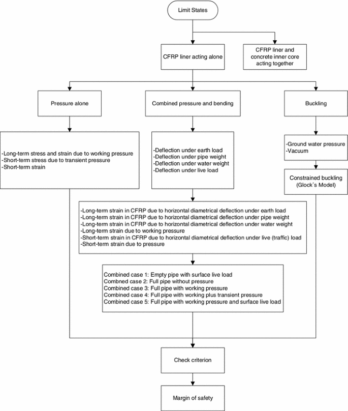
Limit states for Case 1.
-
Case 2 (partially deteriorated): FRP layer and inner concrete core are acting as a composite pipe with the outer core cracked. The limit states for this case are shown in Fig. 2. Partially deteriorated pipes are known to have some broken wires but have not lost their circular shape and do not have irregularities on their surface. For such pipes, hydroblasting will provide a uniform, round surface, resulting in no waviness in the FRP liner that could reduce its buckling strength.
Fig. 2 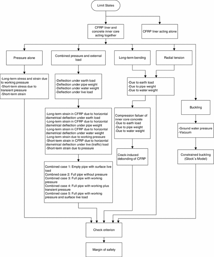
Limit states for Case 2.


The tolerable crack width of water-retaining structures like PCCP, is 0.1 mm (American Concrete Institute 2001). After measuring the crack width and/or evaluation of unevenness, the state of PCCP is decided and the design method is selected. For design purpose, various loadings and reasonable quantities of safety factors should be selected. In this study, as a loading set, working pressure, transient pressure, vacuum pressure, soil cover height, ground water, and surface live load are used. The safety factors and the design procedure follow AWWA C301-07 (American Water Works Association 2007b) and AWWA C304-07 (American Water Works Association 2007a).
Analysis methods for each limit states can be altered with change of conditions. For example, the mono-layer method to get the pipe stress is used here but in some situation multi-layers model may give more reasonable results (Lee 2011). There can also be alternative ways to get the buckling force, pipe deflection, debonding force and so on. It depends on the designer’s choice.
2.1 Deflection
The pipe deflection is the decrease of the vertical diameter of the pipe and the corresponding increase in the horizontal diameter. The increase in horizontal diameter is resisted by the stiffness of the soil at the sides of the pipe. The pipe deflects according to the ratio of the load in the ring to the material stiffness. However, the material stiffness is more complicated since a soil-pipe interaction takes place. The material stiffness becomes a combination of the structural modulus of the pipe and the modulus of the soil. Equation (1) is used to predict the average long-term vertical deflection of pipe (Howard et al. 1995; Howard 1996; Howard 1977). This equation is an empirical relationship based on the Iowa Formula (Spangler and Handy 1982; Spangler 1941) and its revised version (Watkins and Spangler 1958).
where ∆Y (%) is the percent vertical deflection, T f is the time-lag factor, dimensionless, K is the bedding constant (as a general rule, a value of K = 0.1), γ is the backfill unit weight (kN/mm3), h is the depth of cover (mm), EI/r3 is the pipe stiffness factor (kN/mm2), F d is the design factor, dimensionless, and E′ is the modulus of soil reaction (kN/mm2).
The pipe stiffness factor is normally obtained from manufacturer’s literature. Time-lag factor, design factor, and modulus of soil reaction vary according to the type of soil used as the embedment and the degree of compaction of the embedment soil. The strain of pipe due to a deflection under each loading condition is
where ξ is the shape factor, Δ is the deflection (mm), t is the thickness of layer (mm), and D is the diameter to midpoint of layer (mm).
2.2 Buckling and Debonding
The buckling resistance for both Case 1 and Case 2 follows the Glock’s model (Omara et al. 1997). In this application, the small wavy imperfection in radial direction (∆) is assumed to be zero for partially deteriorated condition and it is assumed to be the same as the FRP thickness for fully deteriorated condition. The correction factor from wavy imperfection for buckling resistance is
The ovality due to earth load and pipe weight is
The correction factor from ovality for buckling resistance is
The buckling resistance using Glock’s Model is modified to account for imperfections as in Eq. (6a). In case the FRP and the inner concrete core acting together, the buckling resistance is expressed in Eq. (6b).
The debonding is a behavior that occurs if the force in the FRP cannot be sustained by the substrate, regardless of where the failure plane propagates within the FRP-adhesive-substrate region. To prevent a crack-induced debonding, the FRP strain is limited as in Eq. (7) (American Concrete Institute 2008b; Teng et al. 2001; Teng et al. 2004).
2.3 Margin of Safety
The internal pressure could be short term loading like a water hammering as well as long term loading, and for that reason both short term and long term loading combined together to calculate the total applied pressure. In other cases, the long-term loading is considered the most severe loading condition.
A concept of “margin of safety (MS)” is used to judge if the design satisfies a certain limit state. Each of limit states has its own criteria to be fulfilled by design. The MS is a reciprocal of the criterion. This numerical index shows if the design is OK or not. For example, if the MS is greater than or equal to one, then the design for the limit state is fine. The criteria from AWWA C304-07 are summarized in Table 1, according to the limit states.
3 Example and Result
The 1 mm thick FRP layers are attached to the inside of the deteriorated PCCP and the changes of the MS are examined as the number of the FRP layers changes. Eight limit-states in total are considered. Buckling model, debonding model and mono-layer model presented in the previous sections are used to calculate each limit-state. The load factors and reduction factors follow American Concrete Institute (2008b) and American Society of Civil Engineers (2005). The resultant factor of safety is 3.5 for FRP subjected to long-term loads and 1.9 for FRP subjected to short-term loads. It is 2.2 for concrete in flexure as well as for radial tension between concrete core and FRP layer. It is 2.5 for crack-induced debonding between concrete core and FRP layer. The rerounding factor of 0.77 and the bedding coefficient of 0.09 are used (American Water Works Association 2005).
Figure 3 shows the change of the safety margin of each loading case according to increasing of the FRP layers when FRP acts alone. Figure 4 shows the change of the safety margin of each loading case according to increasing of the FRP layers when FRP and inner core concrete act together.

Margins of safety (FRP acts alone).

Margins of safety (FRP and inner core act along).
When FRP acts alone with only internal pressure, and with the combined internal pressure and the external loads, the MS reaches 1.14 and 1.10 respectively, with seven layers of FRP. When FRP acts alone and considering the buckling, it requires 14 layers to reach the MS of 1. This means quite many FRP layers are required to rehabilitate PCCP when the inner core concrete is cracked. When FRP and core concrete act together subject to the combined internal pressure and the external loads, the MS reaches 1.06 with 9 layers of FRP.
Unlike expectation, there are certain limit-states at which the increase of the reinforcing layers would reduce the MS. For example, when it comes to the inner core concrete crush, the MS is less than 1 with the layers of 11 or more. Thick FRP layer would receive more portions of the applied loads than core concrete. Because of the higher strain limit of FRP, the concrete cracks before the total failure.
Similar trends are observed in debonding between FRP and concrete, and in radial tension between them. Although the MS is not going under 1 in this examination, it is continuously decreasing as more layers are attached. It is thought that the unequal distribution of the loads due to the increasing FRP portion causes the different behavior between FRP and attached inner core concrete.
After inspection of the PCCP, the degree of the deterioration can be informed. If the inner core concrete is already cracked so that the FRP is expected to act alone, it is recommended that more than 14 layers of SCH-41 be applied. If the inner core is deteriorated but still in sound condition so that the FRP is expected to act along with it, then using of nine or ten layers of FRP is recommended.
4 Conclusions
The limit-states of the PCCP with FRP rehabilitation were studied. For design purpose, proper factors of safety were selected. To get the stress and strains of each layer under certain condition, the mono-layer model was used. It was extended to get the stresses in radial direction and tangential direction of the pipe section. This mono-layer model was also developed to be used in a plastic range behavior of thick and thin layered pipe. The Glock’s buckling model (Omara et al. 1997) was modified and used to express FRP behavior. Teng’s debonding limit equation (American Concrete Institute 2008b; Teng et al. 2001; Teng et al. 2004) was introduced for crack-induced debonding of FRP.
Through the analysis, the MS could be obtained for each limit-state. Total eight limit-states were considered: three states for FRP alone case, and five states for FRP and core concrete together case. Conducting an example analysis, the tendency of the MS according to the increase of the FRP layers was obtained. In general, the more FRP reinforcing produces the better performance of the pipe. However, some limit-states, for example, concrete crushing, crack-induced debonding, and radial tension showed opposite results to the general expectation. It may be caused by the increase of the non-uniform stress distribution due to the difference of the material properties as FRP layer getting thicker. It is very important to find the optimal quantities of the FRP layers considering all limit-states. As shown in above example, too much or too little rehabilitation can cause negative effects.
The debonding strain equation used in this example was originally developed for the FRP strengthened concrete beam. There could be some discrepancy in applying it to the PCCP. However, to the best of the author’s knowledge, there is no proper study of PCCP for this topic. In the future studies, experimental data should be obtained to get the strain equation of FRP debonding of the PCCP as it’s done for the concrete beam.
References
American Concrete Institute. (2001). ACI 224R-01 control of cracking in concrete structures. Farmington Hills, MI: ACI.
American Concrete Institute. (2008a). ACI 318 building code requirements for concrete and commentary. Farmington Hills, MI: ACI.
American Concrete Institute. (2008b). ACI 440.2R-08 guide for the design and construction of externally bonded FRP system for strengthening concrete structures. Farmington Hills, MI: ACI.
American Society of Civil Engineers. (2005). ASCE 7-05 minimum design loads for building and other structures. Reston, VA: ASCE.
American Water Works Association. (2005). AWWA M45 fiberglass pipe design, manual of water supply practices. Denver, CO: AWWA.
American Water Works Association. (2007a). Design of prestressed concrete cylinder pipe. Denver, CO: AWWA.
American Water Works Association. (2007b). Prestressed concrete pressure pipe, steel-cylinder type. Denver, CO: AWWA.
Fortner, B. (1999). Main line mending. Civil Engineering,69, 25–42.
Heger, F. J., Zarghamee, M. S., & Dana, W. R. (1990). Limit-states design of prestressed concrete pipe. I: CRITERIA. Journal of Structural Engineering,116, 2083–2104.
Howard, A. K. (1977). Modulus of soil reaction values for buried flexible pipe. Journal of the Geotechnical Engineering Division, ASCE,103, 33–43.
Howard, A. (1996). Pipeline installation. Lakewood, CO: Relativity Publishing.
Howard, A. K., Kinney, L. A., Jr., & Fuerst, R. P. (1995). Prediction of flexible pipe deflection. Denver, CO: U.S. Bureau of Reclamation.
Lee, D. C. (2002). Rehabilitation of large diameter PCCP with composites. San Diego, CA: University of California.
Lee, Y. (2011). Analysis of prestressed concrete cylinder pipes for rehabilitation. Irvine, CA: University of California.
McReynolds, M. (1999). An innovative solution for the repair of the sepulveda feeder. In International Public Works Congress and Exposition. American Public Works Association.
Omara, A. M., Guice, L. K., Straughan, W. T., & Akl, F. A. (1997). Buckling of thin circular pipes encased in rigid cavity. Journal of Engineering Mechanics,123, 1294–1301.
Spangler, M. G. (1941). The structural design of flexible pipe culverts. Ames, IA: Iowa State Engineering Experiment Station Bulletin.
Spangler, M. G., & Handy, R. L. (1982). Soil engineering. New York, NY: Harper & Row.
Teng, J. G., Lu, X. Z., & Ye, L. P. (2004). Recent research on intermediate crack induced debonding in FRP strengthened beams. In Proceedings of the 4th International Conference on Advanced Composite Materials for Bridges and Structures. Calgary, Canada.
Teng, J. G., Smith, S. T., & Chen, J. F. (2001). Intermediate crack induced debonding in RC beams and slabs. Construction and Building Materials,17, 447–462.
Watkins, R. K., & Spangler, M. G. (1958). Some characteristics of the modulus of passive resistance of soil: A study of similitude. Highway Research Board Proceedings,37, 576–583.
Zarghamee, M. S. (1988a). Experimental evaluation of design methods for prestressed concrete pipe. Journal of Transportation Engineering, ASCE,114, 635–655.
Zarghamee, M. S. (1988b). A multilayered model for analysis of composite pipes. In Bruce A. Bennett (Ed.), Pipeline Infrastructure (pp. 136–147). New York, NY: ASCE.
Zarghamee, M. S. (1988c). Predicting prestress losses in prestressed concrete pipe. Concrete International,10, 59–64.
Zarghamee, M. S., & Fok, K. L. (1990). Analysis of prestressed concrete pipe under combined loads. Journal of Structural Engineering,116, 1734–1742.
Zarghamee, M., Ojdrovic, R., & Fongemie, R. (1998). Condition assessment and repair of prestressed concrete pipelines. In Pipeline Division Conference (pp. 703–713).
Author information
Authors and Affiliations
Corresponding author
Rights and permissions
Open Access This article is distributed under the terms of the Creative Commons Attribution License which permits any use, distribution, and reproduction in any medium, provided the original author(s) and the source are credited.
About this article
Cite this article
Lee, Y., Lee, ET. Retrofit Design of Damaged Prestressed Concrete Cylinder Pipes. Int J Concr Struct Mater 7, 265–271 (2013). https://doi.org/10.1007/s40069-013-0057-9
Received:
Accepted:
Published:
Issue Date:
DOI: https://doi.org/10.1007/s40069-013-0057-9