- Open access
- Published:
Hysteretic Behavior of Conventionally Reinforced Concrete Coupling Beams in Reinforced Concrete Coupled Shear Wall
International Journal of Concrete Structures and Materials volume 11, pages 599–616 (2017)
Abstract
This paper presents the experimental results of four full-scale coupling beams in which only horizontal reinforcements are placed, without diagonal reinforcements, with the aim to develop reinforcement details for coupling beams used in connecting side walls in a wall-slab structural system. Each coupling beam specimen was designed according to the deep-beam design procedure that does not use diagonal reinforcements and that is found in current standards. Two cases for basic deep-beam design specimens were investigated wherein (1) U-type reinforcement was added to prevent sliding shear failure of the joints and (2) horizontal intermediate reinforcements were placed. The coupling beam specimens were fabricated with a shear span-to-depth ratio (aspect ratio) of 1.68 and were connected to walls only by horizontal reinforcements, i.e., without diagonal reinforcement. The experimental results indicate that the strength of the beams was about 1.5 times the designed strength of a strut-and-tie model, which suggests that the model is available for predicting the strength of coupling beams with conventional reinforcement layouts such as horizontal and transverse reinforcement bars. The deformation capacity of these conventionally reinforced concrete coupling beams ranged from 1.48 to 3.47% in accordance with the reinforcement layouts of the beams. Therefore, this study found that the performance of conventionally reinforced concrete coupling beams with an aspect ratio of 1.68 can be controlled through the implementation of reinforcement details that include U-type reinforcement and the anchorage of intermediate horizontal bars.
1 Introduction
Structural walls can serve as an effective structural system to resist lateral loads, such as earthquakes or winds, in high-rise buildings. Coupling beams that connect these walls, which behave independently at each floor, can improve the building’s lateral resistance capacity. Eurocode 8 (2004) defines a coupling beam as a beam that is designed to reduce the bending moment that acts on the wall by about 25% compared to the case where the wall behaves independently. Figure 1 shows, however, that a greatly amplified nonlinear deformation in the coupling beam is required, even if little deformation occurs in the walls. That is, the coupling beam should not only have the ability to resist the bending moment but should also possess a certain deformation capacity because it plays a role in inducing the ductile behavior of the wall. In this regard, Eurocode 8 (2004) states that a coupling beam can be utilized as the beam in the moment-resistant frame only in those cases where it is dominated by the flexural behavior, that is, when the ratio of the length (l) to the depth (h) is more than 3.0 or the beam can resist the shear force by diagonal reinforcements.

Structural behavior of coupling beam.
According to American Concrete Institute (ACI) code (2014), although a coupling beam can be designed according to the usual beam design method where l/h ≥ 4, as shown in Fig. 2, it can nonetheless be reinforced with diagonal cages in the case of l/h < 4. Specifically, a coupling beam with l/h < 2 and whose factored shear force (V u) is greater than \( 4 \cdot \lambda \cdot \sqrt {f_{ck} \cdot A_{cw} } \) is required to be designed with diagonal cages at the center of the span. Where fck is the compressive strength of the concrete and Acw is the cross-sectional area of the web of the beam. The ACI code also requires that the nominal shear strength of the beam should be developed only through diagonal reinforcements and it should be confined sufficiently by transverse reinforcements, as shown in Fig. 3a. Or, the entire beam should be confined by sufficient transverse reinforcement, as shown in Fig. 3b, so that the diagonal reinforcements cannot undergo compressive buckling.

Design concept for coupling beam in ACI 318 (2011).

Reinforcement details for short coupling beam in ACI 318 (2011). a Confining diagonal bars, b Confining beam.
The basic concept behind reinforcements for coupling beams for a special structural wall is to confine the beam using closely spaced transverse reinforcements to prevent compressive buckling of the diagonal reinforcements. Accordingly, the currently used codes (ACI 2014; Eurocode 8 2004; Korea Concrete Institute (KCI) 2012) for different areas of the world stipulate that at least four diagonal reinforcements should be placed and laterally confined. Such construction details, however, make actual construction difficult at field sites. Consequently, the current ACI code (2014) requires that lateral confinement of coupling beams should be used instead of diagonal reinforcements, as shown in Fig. 3b, which were recommended in the ACI Committee 318 2011 edition of the ACI code (ACI 2011). These construction details, however, still pose difficulties in construction due to the excessive use of lateral confinement reinforcements and diagonal reinforcements.
In the current standards (ACI 2014; Eurocode 8 2004; KCI 2012), all the shear forces and moments that act on coupling beams are assumed to be borne only by the diagonal reinforcements. Therefore, transverse and longitudinal reinforcements that confine the diagonal reinforcements are not reflected in the design at all. Consequently, all the reinforcements that are placed in the longitudinal direction of the beam are cut off at the interface, without being affixed to the walls. In other words, plastic behavior of the diagonal reinforcements is encouraged in order to dominate the behavior of the coupling beams at the ends of such beams where the moment and shear forces are greatest. Such construction details may induce sufficient plastic behavior of the coupling beam but may pose difficulties in construction, as stated earlier, when the shear and longitudinal reinforcements that are placed for the lateral confinement of the diagonal reinforcements are excessive in quantity. In particular, in the case of a wall-slab type apartment building with no columns, the walls may be as thin as 200 mm or 300 mm, making rebar placement especially difficult. Furthermore, the mandatory placement of diagonal reinforcements, which pose difficulty in construction, makes it very difficult to perform rebar work in the actual field, which in turn may lead to faulty construction.
A performance-based design method (TBI Guidelines Working Group 2010) was developed recently for the design of reinforced concrete (RC) members. Thus, the development of construction details for coupling beams that can be selected according to the design requirements also is needed. Specifically, depending on the shear span-to-depth ratio and shear stress of the coupling beam, diagonal reinforcements should be used if high deformation capacity is required. If not, alternative details must be developed. Because such walls have high stiffness values, the shearing rate of the lateral force is also high, but the actual deformation is small. For example, a wall-slab type of structure with no columns has numerous long walls that experience little deformation. Therefore, the amount of deformation that is required for the coupling beams that connect these walls likewise becomes relatively small. In other words, high deformation capacity is not required for the coupling beams; thus, suitable construction details for coupling beams should be investigated.
In order to develop such reinforcement details for coupling beams that connect walls with less deformation in a wall-slab structural system, this study sought to design coupling beams in which only conventional reinforcements are placed, without diagonal reinforcements, and thus to examine the hysteretic behavior of the coupling beams based on the results of cyclic loading tests for proposed reinforcement details.
2 Review of Previous Studies
The significant damage of conventional RC coupling beams during the Alaska earthquake that occurred in 1964 showed that coupling beams with orthogonal reinforcements that consist of traditional longitudinal and transverse reinforcements are susceptible to severe damage under large shear reversals. Paulay and Binney (1974) proposed the idea of placing two intersecting diagonal reinforcement groups, confined by closely-spaced transverse reinforcements, for shear-dominant RC coupling beams. Many researchers (Barney 1976; Shiu et al. 1978; Tegos and Penelis 1988; Tassios et al. 1996; Galano and Vignoli 2000; Kwan and Zhao 2002; Fortney 2005; Naish 2010) have shown that diagonal reinforcement groups are effective in improving the strength, ductility, and energy dissipation capacity of RC short coupling beams. Diagonal reinforcement groups are generally recognized as the most effective type of reinforcement detail for providing ductile behavior of RC short coupling beams that have a span-to-depth ratio of less than or equal to 2.0. Placing two groups of diagonal bars in RC coupling beams that have an aspect ratio of less than 4.0 has been specified since 1995 in the ACI Building Code (ACI 318-95 1995), which specifies that each group of diagonal bars shall have the same quantity as the transverse reinforcements for the columns in the special moment frame to suppress the buckling of each diagonal-bar group. However, the placement of transverse bars around the diagonal reinforcement groups, as specified in ACI 318-05, leads to significant construction difficulties. In order to overcome such difficulties, ACI 318-08 includes an alternative detail option where transverse reinforcement is placed around the beam’s full section, without directly placing transverse reinforcement around the diagonal bar groups. However, it is almost impossible to place diagonal reinforcement groups at a right angle to all the required transverse bars required for the diagonal confinement and full-section confinement found in ACI 318-05 (2005) and ACI 318-08 (2008), respectively (Hajyalikhan 2015).
To resolve these construction difficulties, several alternative construction details for RC short coupling beams have been considered, including rhombic reinforcement, diagonal reinforcement without transverse ties, bent-up reinforcement, double beams, and long and short dowel reinforcement layouts (Tegos and Penelis 1988; Tassios et al. 1996; Galano and Vignoli 2000; Hajyalikhan 2015). However, none of these construction details allows for performance that is equivalent to that of coupling beams strengthened with bundled diagonal reinforcements according to the existing details specified in the standards and that significantly improve constructability. Recently, as the building design concept has changed to performance-based design, improving constructability and reducing economic costs have been accomplished by utilizing coupling beams with proper reinforcement details that are based on the required deformation capacity under the design loads rather than based on the aspect ratio, as in the current standard.
More recently, studies have focused on developing construction details for seismic performance evaluation and improvement of coupling beams that are strengthened with horizontal and vertical reinforcements. Breña and Ihtiyar (2010) investigated the effects of different amounts of longitudinal and transverse reinforcement on the seismic behavior of four RC coupling beams and discussed the strength, deformation components, and response parameters that are needed to construct backbone curves for conducting nonlinear analyses of a coupled shear wall system. Hajyalikhan (2015) proposed a simplistic reinforcement scheme that consists of two separate cages that are similar to those used for typical beams in RC special moment frames to minimize the construction problems that are associated with diagonal reinforcement groups. Hajyalikhan (2015) reported that proposed details for RC short coupling beams can transform shear-dominated, brittle behavior into flexure-dominated, ductile behavior. Cai et al. (2016) conducted experimental tests using steel fiber-reinforced concrete (SFRC) coupling beams with conventional reinforcements and proposed a simplified model that applies the Mohr–Coulomb failure criterion to predict the seismic shear strength of SFRC coupling beams. Their test results indicate that the inclusion of steel fibers can enhance the seismic performance of SFRC coupling beams and that their proposed model provides accuracy and reliability. Lim et al. (2016) investigated the seismic performance of intermediate aspect ratio coupling beams using proposed alternatives to mitigate the construction difficulties associated with diagonal reinforcement by combining conventional and diagonal reinforcement construction details. Nabilah and Koh (2017) tested four conventional RC coupling beams with aspect ratios of 2.5 and 3.1 and reported that the shear stiffness of an intermediate length coupling beam was reduced by 0.1% of the initial stiffness value upon the yielding of the reinforcement.
In Korea since the 2000s, numerous researchers have conducted studies to evaluate performance and simplify construction details of coupling beams. For example, Park and Yun (2011) investigated the seismic performance of strain-hardening cement-based composite (SHCC) coupling beams that contained different types of reinforcement. They found that ductile cement-based composites such as SHCC are effective in improving the ductility and strength of shear-dominant coupling beams. Shin et al. (2014) tested three high-performance fiber-reinforced cement composite (HPFRCC) coupling beams with an aspect ratio of 3.5. Their test results showed that HPFRCC greatly contributes to the reduction in crack damage and shear distortion in slender coupling beams. Jang et al. (2015) examined the feasibility of replacing additional transverse reinforcement that is required for short coupling beams that contain 1.5% hooked-end steel fiber. Also, the Korea Land and Housing Institute (2012, 2014) proposed simplified reinforcement details for transversely confined diagonal reinforcement in short coupling beams in coupled shear walls.
3 Deformation Capacity Required for Coupling Beams
The behavioral characteristics of coupling beams are related to the deformation of the lateral forces of the walls to which the beam is connected, as shown in Fig. 1. The beam exhibits the deformation of a double curvature due to the deformation of the left and right walls. In the figure, the drift required for the beam is the same as the story/floor drift of the walls. If the stiffness of the left wall is different from that of the right wall, the drift of the wall with less stiffness will be greater than the one that is more stiff. In this case, it is desirable to consider the drift of the wall that has the large deformation also as the drift of the beam. The drift required for the walls can be determined by the stiffness values of all the walls on the floor if the story drift of the floor is considered the same due to the diaphragm behavior of the floor. However, determining the drift required for each wall separately is preferable in order to evaluate whether the coupled walls provide sufficient ductility with respect to the largest drift. That is, the drift required for the coupling beams cannot be less than that required for the walls.
The ACI code (2007) provides a recommendation for the application of precast concrete walls, which is not covered in the design criteria, to an area that experiences strong earthquakes if the performance can be proven through appropriate performance tests and analyses. In addition, the ACI presents guidelines for related tests to evaluate whether the structural members provide sufficient strength, stiffness, ductility, and energy dissipation capacity via performance testing. These guidelines also are quoted in the National Earthquake Hazards Reduction Program (NEHRP) provisions for seismic regulations for new buildings (NEHRP 450-1 2003).
Equation (1), defined in NEHRP 450-1, expresses the required displacement angle as ductility capacity for a wall. Here, the ductility capacity is the same as for RC, which means that the ductility should be retained without a rapid drop in the yield strength with respect to the drift that is (1) 1.5 times the design displacement or (2) from a minimum of 0.8 up to 2.5% according to the shear span-to-depth ratio, which is the ratio of the height to the length of the shear wall. Equation (1) is based on a study by Seo et al. (1998) that analyzed the experimental results of RC shear walls. Then, Hidalgo et al. (2002) reanalyzed the minimum and maximum displacement angles of the specimens and adjusted them to 0.8 and 2.5%, respectively. This adjustment was needed to show maximum shear wall behavior of more than 2.5% in cases of shear wall behavior.
where h w is the height of the wall for a prototype structure, and l w is the length of the entire wall in the direction of the shear force.
The aforementioned relationship can be used to calculate the maximum drift required for wall-slab buildings designed with special shear walls. In South Korea, a typical wall-slab type apartment usually has a floor height of 2.7 m to 3.0 m and a wall thickness of 300 mm. Because the frame behavior governs when the wall length is short or the aspect ratio is too large, ACI (2014) regards these walls as pier walls and requires that they be designed as columns in a frame. In this case, the coupling beams should be in accordance with the strong column/weak beam design principle. If the beams are designed as coupling beams in special shear walls, the beams will be overdesigned, and thus, a failure is likely to occur in wall. The conditions for pier walls are l w /b w ≤ 6 and h w /l w ≥ 2.0. For wall-slab type buildings in Korea, the condition in which the wall is not classified as a pier wall is when the length of the wall is more than 6 × 300 mm = 1800 mm or h w /l w < 2.0. The range of the expected h w /l w is 1.5–2.0, and when it is applied to Eq. (1), the required drift ranges from 1.51 to 1.84, as shown in Fig. 4. That is, ductile behavior is required for beams that are connecting the walls within this range, and thus, the ability to absorb the drift of the walls is required for the coupling beams.

Drift of wall in wall-slab structure.
4 Experiment Plan
4.1 Design of the Specimens
Four full-sized coupling beam specimens were designed and fabricated according to the deep-beam design in the current KCI standard (KCI 2012). This design is without diagonal reinforcements and considers constructability and excess strength. After the basic design according to the deep-beam design concept, two cases were considered: (1) U-type reinforcement was added to prevent sliding shear failure of the joints and (2) horizontal intermediate reinforcements were placed. Table 1 presents the specimen data, and Fig. 5 shows the construction details for each specimen.

Specimen configurations and reinforcement details. a B-1-H, b B-1-HA, c B-2, d B-2-H.
Basically, all the specimens were designed based on the strut-and-tie model, as shown in Fig. 6. According to the current standard (KCI 2012), a member, where l n is less than four times the depth of the member, or on which the load is applied within a distance of two times the depth of the member from the support and a compression strut can be formed between the load-applied point and the support, can be designed using the strut-and-tie model if the applied shear force is less than \( (5 \cdot \lambda \sqrt {f_{ck} } /6)b_{{}} \cdot d \) and the ratio of the shear span to depth, l n /d is less than 2.0. The l n /d of each specimen used in this study was 908/540 = 1.68, which is less than 2.0.

Truss model for short coupling beam.
The amount of reinforcement for each tie was estimated using Eqs. (2) and (3), and the width of the strut was calculated using Eq. (4). The minimum requirements for the vertical and horizontal reinforcements were examined using Eqs. (5) and (6).
where A st is the required area of reinforcement; F u,DB , F u,BC , and F u,DE are the forces acting on members DB, BC, and DE, respectively; \( \varphi \) is the strength reduction factor; f y is the yield strength of the reinforcement; w req . is the required width of the compressive strut; β s is the coefficient for the equivalent stress block; f ck is the compressive strength of concrete; b is the width of the beam; and A si is the total area of the distributed reinforcement at spacing s i in the ith direction of the reinforcement that crosses a strut at an angle γ i to the axis of the strut.
In addition, the spacing of the transverse reinforcements was decided by using Eq. (7) to satisfy the lateral-confinement condition, as shown in Fig. 5b, so that the cross-ties in the vertical and horizontal directions would not exceed 200 mm. Appendix provides the design procedures for each specimen.
where d is the effective depth.
For the B-1-H specimen, 3-HD22 (1161.3 mm2) was placed as flexural reinforcement on the upper and lower parts in accordance with the previously described design process. The horizontal reinforcement 8-HD10 and the stirrup HD13@100 were decided using Eqs. (5), (6), and (7) for the minimum reinforcements in the vertical/horizontal direction. The horizontal reinforcement 8-HD10 at the center of the section is the reinforcement for the lateral confinement of the beam rather than for the flexural strength, but this reinforcement was affixed sufficiently to the walls so that it could contribute to the flexure and shear at the joints. In addition, headed reinforcement was used instead of a 90-degree hook to improve the lateral-confinement performance.
The B-1-HA specimen was almost the same as the B-1-H specimen, but its reinforcement for the lateral confinement of the beam was cut off at the beam-wall interface, without being affixed to the walls. To enhance the confinement effect by increasing the number of reinforcements, 2-(HD22 + HD16) (1171.4 mm2) was placed as the upper and lower reinforcements of the beam; these reinforcements were affixed to the walls. Unlike the B-1-H specimen, horizontal reinforcement 8-HD10 was not affixed to the wall, so these reinforcements did not contribute to the flexure at the joints. For the beam stirrup, 2-(HD13 + HD10) was placed at 100-mm intervals.
The B-2 and B-2-H specimens were strengthened further using U-type bars to control any sliding shear at the joints that may occur using the construction details for the B-1-HA specimen. The number of U-type bars was calculated using Eqs. (8) and (9). As for the shape of the anchoring cross-ties, the B-2 specimen had 135- and 90-degree hooks for each end, respectively, whereas the B-2-H specimen used headed reinforcements. Shin et al. (2016) reported the effectiveness of confining core concrete using headed cross-ties.
where A vf is the area of reinforcement for friction design.
4.2 Material Properties
Concrete cylinders, 100 mm in diameter and 200 mm in height, were fabricated for compressive strength tests conducted at 28 days. The compressive strength value was found to be 28.7 MPa. Table 2 provides the tensile test results for the reinforcements used.
4.3 Test Method and Measurements
Figure 7 shows the test set-up wherein coupling beams were affixed to the lower part of the wall and horizontal displacement was induced in the upper part of the walls. Ball jigs were installed on both sides at the center of the upper part of the wall to prevent out-of-plane deformation when horizontal displacement was applied. In addition, a roller was installed on the upper part to slide the upper part of the wall in the loading direction without rotating it. Bolts were used to connect the loading frame to the upper part of the wall, and an actuator with a 1000-kN capacity was installed at the central axis of the specimen to apply horizontal force. Strain gauges were attached to the diagonal, horizontal, and vertical reinforcements to measure the deformation and yielding period of the reinforcements.

Test setup for short coupling beams.
Figure 8 shows that cyclic loading was applied with load control up to three cycles, and then by two cycles per the same displacement from drifts of 0.2 up to 6.0%. The loads of the specimens were measured by a load cell attached to the actuator. Figure 9 shows the lateral displacement that was measured by the linear variable displacement transducers (LVDTs) at the center of the upper and lower parts of the wall and at the joints. The rotation of the upper part of the wall was measured also.

Loading history.

Locations of a LVDT locations and b strain gauge locations.
5 Experimental Results
5.1 Cracking and Failure Shape
Figure 10 presents the final failure modes of the specimens. The cracking process for each specimen is described below.

Failure patterns of specimens. a B-1-H, b B-1-HA, c B-2, d B-2-H.
The failure of the B-1-H specimen revealed that initial cracks occurred along the interface at the corner of the joint between the coupling beam and the upper and lower parts of the wall at the drift of 0.2% and that cracks at the upper right part of the coupling beam increased at 1.0%. At the drift of 1.4%, many horizontal reinforcements yielded, and the width of the cracks increased rapidly as the load increased. Finally, delamination of the concrete cover at the upper part of the coupling beam occurred at the drift of 2.2%. Failure did not occur evenly at the joints of the two walls, but was concentrated only at the part of the joint that was connected to the upper wall.
For the B-1-HA specimen, initial horizontal cracks occurred at the center and at the lower left and upper right corners of the coupling beam at the positive loading of 0.2% drift. At the drift of 0.4%, the inclined cracks progressed at the upper and lower parts and at the central part of the beam. At the drift of 1.0%, the width of the inclined cracks increased, and delamination of the concrete cover occurred at the upper and lower parts of the coupling beam. Finally, at the drift of 3.0%, delamination of the concrete surface occurred at the upper and lower parts of the coupling beam. Then, plastic hinges formed at both ends of the coupling beams.
In the case of the B-2 specimen, initial horizontal cracks occurred at the left interface between the coupling beam and the lower parts of the wall at the positive loading of 85.23 kN, and diagonal cracks began to appear as the load increased. In addition, as the diagonal cracks rapidly increased at the drift of 0.4%, they were found to have been distributed throughout the beam. At the drift of 1.0%, delamination in the concrete surface occurred at the upper left part of the beam, and the width of the diagonal cracks increased by 1.4%. The test was terminated at the drift of 1.8%. As diagonal tension failure occurred at the center of the span, not at the interface with the walls, delamination in the concrete surface near the cracks occurred, leading to brittle fracture.
For the B-2-H specimen, initial cracks occurred at the left interface of the lower part of the wall and the right interface of the upper part of the wall in the first cycle of positive loading at the drift of 0.2%, and diagonal cracks occurred near the center of the coupling beam at 0.4% drift. Finally, the specimen underwent brittle failure as partial delamination of the concrete cover occurred at the center of the coupling beam at the drift of 2.2%. The U-type reinforcement that was placed to prevent sliding shear failure of the joints is thought to have contributed to the flexure of the joint between the coupling beams and the walls so that shear failure occurred in the beam.
5.2 Load–Drift Curves
Figure 11 presents the load–drift curves of the specimens. Table 3 shows the yield strength, maximum strength, failure strength, and displacements at those states for each specimen. The yield point was set at 75% of the maximum load, and the failure point was set to the time when the load was reduced by 25% (0.75 Pm) after the peak point was reached. The absence of data in the table indicates that the test was terminated at a state where the load had not reached the point of 0.75 Pm beyond the peak point. The B-1-H specimen exhibited a deformation capacity of about 2% drift and exceeded the design strength, but significant pinching appeared in the loading zone. The strength of the B-1-HA specimen also exceeded the design strength, but a reduction in strength after the peak was more severe in the B-1-HA specimen than in the B-1-H specimen. The joints between the beam and the wall were found to have a higher strength value than the designed joints even if they were connected only by the upper and lower horizontal reinforcements. The B-2 and B-2-H specimens that had been strengthened with additional U-type reinforcements showed a sharp reduction in strength after reaching the maximum force, even though the plastic hinges moved to the beam rather than to the beam-wall interface. These two specimens eventually failed with severe x-shaped diagonal cracks, indicating that they all dominated by shear failure. All the specimens exhibited significant pinching phenomena at reloading after the load reversal, thus showing no effective resistance to shear.

Load–drift curves of specimens. a B-1-H, b B-1-HA, c B-2, d B-2-H.
Figure 12 presents the envelope curves of the specimens. The B-1-H specimen exhibited the greatest strength and ductility capacity, showing a deformation capacity of about 2% drift. The B-2 specimen, to which U-type reinforcements were added, showed lowest strength and deformation capacity. As shown in Fig. 13, if a plastic hinge forms at the wall-beam joint, the deformation will be dispersed, but if it is concentrated at the center of the beam, brittle failure is likely to occur because the shear deformation is concentrated. In the case of the B-2 and B-2-H specimens with U-type reinforcements at the joints, plastic hinges formed at the center of the beam, because the wall-beam joints were strengthened. Therefore, the overall behavior seemed to be extremely brittle as the deformation was concentrated at the center of the beam in the form of shear deformation.

Envelope curves.

Plastic behavior that corresponds to formation of plastic hinges. a Formation of plastic hinge at wall-beam joints, b Formation of plastic hinge at beam center.
The strength of a coupling beam that is connected to walls with only horizontal reinforcements, without the use of diagonal reinforcements, was calculated based on the strut-and-tie model. As shown in Table 3, this strength value was found to be 1.21–1.64 times higher than the design strength. Except for the B-2 specimen with a significantly lower strength value in the negative direction, the ratios were 1.46–1.64 times higher than the design strength, indicating that the average is about 1.5 times the design strength. The drift of the specimens at the maximum load ranged from 1.13 to 2.11%. Compared to the B-1 series specimens whose horizontal reinforcements of the beams were anchored in the walls, the B2 series specimens whose main bars were anchored in the walls showed low drift percentages. The wall drift of Eq. (2) becomes 1.63% when it is considered as the required drift until failure. When this value is compared with the test results, all the specimens, except for the B-2 specimens, can be said to have exceeded the required drift of 1.63%. Of course, more than 1.5 times the design response displacement of the building is required for an actual building, which needs to be taken into consideration.
5.3 Energy Dissipation Capacity
Figure 14 presents the dissipation energy and accumulated energy of the specimens for each displacement step. On the whole, the cumulative dissipation energy values of all the specimens are very similar. The B-1-HA specimen shows similar dissipation energy up to the drift of 2% despite slightly low strength, as the number of horizontal reinforcements anchored in the wall is less than that of the B-1-H specimen. In the case of the B-2 specimen, the energy value per cycle is lower than for the other specimens. This outcome is probably due to its brittle behavior whereby the strength suddenly decreased after the maximum load was reached as shear failure occurred in the beam.

Comparison of dissipated energy values: a accumulated energy, b cyclic energy.
5.4 Reinforcement Strains
Strain distributions of the horizontal reinforcements were observed at the wall-beam joints. The specimens with horizontal reinforcements anchored in the wall exhibited a similar degree of deformation as the interface with the wall and at the vicinity of 0.5 d (d: effective depth of coupling beam). Figure 15 shows the deformation of the horizontal reinforcements located at 0.5 d from the wall-beam joints. The B-1-H specimen exhibits low deformation of the horizontal reinforcement at the center, but the B-2 and B-2-H specimens with U-type reinforcements show greater deformation of the reinforcements at about 1% drift. This outcome is due to the fact that the flexural deformation caused by the upper and lower horizontal reinforcements was dominant at the wall-beam joints in the case of the B-1-H specimen, whereas the shear deformation at the center of the beam dominated for the B-2 and B-2-H specimens. This phenomenon also can be seen in Fig. 16 that shows the stirrup strain response of each specimen. For the B-2 and B2-H specimens, the stirrup at the center yielded, and the deformation increased sharply after the drift of 1%. In the case of the B-1-H specimen, the strain of the stirrup at the center of the beam increased, but the degree of increase was less than that of the specimens with U-type reinforcements. For the B-1-HA specimen, the overall stirrup strain was low, and was remarkably low especially at the center of the beam. This finding suggests that in cases where the wall and the beams are connected only by upper and lower horizontal reinforcements, the behavior is dominated by the flexural behavior of the joints, and the stress from the wall may not be transferred properly to the coupling beam when the connection is weak.

Strain levels of horizontal bars. a B-1-H, b B-1-HA, c B-2, d B-2-H.

Strain levels of stirrups. a B-1-H, b B-1-HA, c B-2, d B-2-H.
From the comparison of the B-2 and B-2-H specimens tested to investigate the confinement effect of headed cross ties, the cross ties with the standard hook shows a slightly greater strain than the headed cross ties. Therefore, no further increase in the confinement effect is likely when headed bars are used as the horizontal and vertical cross ties.
6 Conclusions
An experiment on four full-scale coupling beam specimens was conducted to investigate the hysteresis characteristics of the coupling beams with horizontal reinforcements instead of diagonal reinforcements for wall-slab structural system. The study used reinforcement details for the connection between the beam and the wall as variables, based on reinforcement details required by current standards, to investigate the behavioral characteristics of coupling beams whose shear span-to-depth ratio is less than 2.0 and where only conventional reinforcement layouts are placed, i.e., without diagonal reinforcements. The following conclusions were drawn based on the test results.
-
(1)
Coupling beams whose shear span-to-depth ratio was 1.68 and which were connected to walls only by horizontal reinforcements, without diagonal reinforcement, showed strength that is about 1.5 times the design strength for a strut-and-tie model, thus indicating that proper design strength is possible using these construction details. Overall, the deformation capacity was about 2%, which indicates a certain amount of deformation capacity. A pinching phenomenon, however, that occurred after the load reversals indicated a low level of energy dissipation.
-
(2)
Horizontal reinforcements that were anchored in the walls for the lateral confinement of the beam led to an increase in beam strength. Even in cases where part of the horizontal reinforcement was not anchored into the wall, the design strength and a certain degree of ductility capacity were provided, and plastic hinges could be induced completely in the wall-beam joints. However, the strength gradually decreased after reaching the maximum force, which suggests that if the wall and beams are connected only with upper and lower horizontal reinforcements, the overall behavior is dominated by the flexural behavior of the joints, and the stress from the wall may not be transferred properly to the coupling beam when the connection is weak.
-
(3)
A comparison of the B-2 and B-2-H specimens indicates that the connection reinforcement used in standard hook construction details can lead to a slightly high strain distribution. Therefore, no further increase in the confinement effect would be expected in cases where headed reinforcements are used as the connection reinforcement.
-
(4)
When U-type reinforcements were placed at the joints to control slippage due to the plasticization of the joints, excessive shear deformation occurred as plastic hinges were induced into the center of the beam, without forming at both ends. Consequently, brittle failure occurred when only horizontal reinforcements were placed.
References
ACI Committee 318. (1995). Building code requirements for structural concrete (ACI 318-95) and commentary. Farmington Hills, MI: American Concrete Institute.
ACI Committee 318. (2005). Building code requirements for structural concrete (ACI 318-05) and commentary. Farmington Hills, MI: American Concrete Institute.
ACI Committee 318. (2008). Building code requirements for structural concrete (ACI 318-08) and commentary. Farmington Hills, MI: American Concrete Institute.
ACI Committee 318. (2011). Building code requirements for structural concrete (ACI 318-11) and commentary. Farmington Hills, MI: American Concrete Institute.
ACI Committee 318. (2014). Building code requirements for structural concrete (ACI 318-14) and commentary. Farmington Hills, MI: American Concrete Institute.
American Concrete Institute. (2007). Acceptance criteria for special unbonded post-tensioned precast structural walls based on validation testing. ITG-5.1M-07.
Barney, G. B. (1976). Earthquake resistant structural walls-tests of coupling beams: Progress report. Research and Development Construction Technology Laboratories.
Breña, S. F., & Ihtiyar, O. (2010). Performance of conventionally reinforced coupling beams subjected to cyclic loading. Journal of Structural Engineering, 137(6), 665–676.
British Standard. (2004). Eurocode 8: Design of structures for earthquake resistance. European Committee for Standardization.
Cai, G., Zhao, J., Degée, H., & Vandoren, B. (2016). Shear capacity of steel fibre reinforced concrete coupling beams using conventional reinforcements. Engineering Structures, 128, 428–440.
Chadwell, C., & Imbsen, R. (2004). XTRACT: A Tool for Axial Force - Ultimate Curvature Interactions, Conference proceeding, Structures 2004: Building on the Past, Securing the Future, 1–9, United States.
FEMA. (2003). NEHRP Recommended Provisions for Seismic Regulations for New Buildings and Other Structures. FEMA 450-1.
Fortney, P. (2005). Next generation coupling beams. Ph.D. Dissertation, Department of Civil and Environmental Engineering, University of Cincinnati.
Galano, L., & Vignoli, A. (2000). Seismic behavior of short coupling beams with different reinforcement layouts. ACI Structural Journal, 97(6), 876–885.
Hajyalikhan, P. (2015). Experimental study on seismic performance of reinforced concrete coupling beams and rectangular squat walls with innovative reinforcement configurations. Doctoral Thesis, The University of Texas at Arlington.
Hidalgo, P. A., Ledezma, C. A., & Jordan, R. A. (2002). Seismic behavior of squat reinforced concrete shear walls. Earthquake Spectra, 18(2), 287–308.
Jang, S. J., Kang, D. H., Ahn, K. L., Park, W. S., Kim, S. W., & Yun, H. D. (2015). Feasibility of using high-performance steel fibre reinforced concrete for simplifying reinforcement details of critical members. International Journal of Polymer Science. https://doi.org/10.1155/2015/850562.
Korea Concrete Institute. (2012). Korea structural concrete design code and commentary. Seoul: Kimoondang. (in Korean).
Korea Land & Housing Institute. (2012). Improvement for reinforcement details of the coupling beam and special shear walls. Research Report 2014-45, Yuseonggu, Daejeon, Republic of Korea.
Korea Land & Housing Institute. (2014). Practical use of an alternative detail of the coupling beam in special shear walls. Research Report 2014-45, Yuseonggu, Daejeon, Republic of Korea.
Kwan, A., & Zhao, Z. (2002). Cyclic behaviour of deep reinforced concrete coupling beams. Proceedings of the Institution of Civil Engineers: Structures And Buildings, 152(3), 283–293.
Lim, E., Hwang, S. J., Cheng, C. H., & Lin, P. Y. (2016). Cyclic tests of reinforced concrete coupling beam with intermediate span-depth Ratio. ACI Structural Journal, 113(3), 515.
Nabilah, A. B., & Koh, C. G. (2017). Experimental study of intermediate length coupling beams subjected to monotonic load. KSCE Journal of Civil Engineering, 21(7), 2807–2813.
Naish, D. A. B. (2010). Testing and modeling of reinforced concrete coupling beams. Los Angeles, CA: University of California.
Park, W. S., & Yun, H. D. (2011). Seismic performance of pseudo strain-hardening cementitious composite coupling beams with different reinforcement details. Composites Part B: Engineering, 42(6), 1427–1445.
Paulay, T., & Binney, J. R. (1974). Diagonally reinforced coupling beams of shear walls, shear in reinforced concrete, SP-42 (pp. 579–598). Farmington Hills, MI: American Concrete Institute.
Seo, S., Lee, L., & Hawkins, N. M. (1998). The limiting drift and energy dissipation ratio for shear walls based on structural testing. Journal of the Korea Concrete Institute, 10(2), 335–343.
Shin, M., Gwon, S. W., Lee, K., Han, S. W., & Jo, Y. W. (2014). Effectiveness of high performance fiber-reinforced cement composites in slender coupling beams. Construction and Building Materials, 68, 476–490.
Shin, H. O., Yoon, Y. S., Cook, W. D., & Mitchell, D. (2016). Enhancing the confinement of ultra-high-strength concrete columns using headed crossties. Engineering Structures, 127, 86–100.
Shiu, K. N., Barney, G. B, Fiorato, A. E., & Corely, W. G. (1978). Reversing load tests of reinforced concrete coupling beams. Proceedings of the Central American Conference on Earthquake Engineering, San Salvador.
Tassios, T. P., Moretti, M., & Bezas, A. (1996). On the behavior and ductility of reinforced concrete coupling beams of shear walls. ACI Structural Journal, 93(6), 711–720.
TBI Guidelines Working Group. (2010). Guidelines for performance-based seismic design of tall buildings-version 1.0. Report No. 2010/05, Pacific Earthquake Engineering Research Center.
Tegos, I. A., & Penelis, G. G. (1988). Seismic resistance of short columns and coupling beams reinforced with inclined bars. ACI Structural Journal, 85(1), 82–88.
Acknowledgement
This research was supported by a grant from the Korea Land & Housing Institute. And this work was also supported by the Brain Korea 21 Plus Project of Dept, of Architectural Engineering, Chungnam National University in 2017.
Author information
Authors and Affiliations
Corresponding author
Appendix: Design of specimen
Appendix: Design of specimen
<Design condition>
-
1.
Design loads
$$ V_{u} = 408\,{\text{kN}} $$$$ M_{u} = \frac{{V_{u} \times l_{n} }}{2} = \frac{{(408 \times 10^{3} ) \times 908}}{2} = 185.3\,{\text{kN}} \cdot {\text{m}} $$ -
2.
Check shear strength
Use D22 and D13 as longitudinal bar and stirrup, respectively.
$$ d = h - 40\,{\text{mm}} - 12.7\,{\text{mm}} - 11.1\,{\text{mm}} = 526.2\,{\text{mm}} $$$$ \begin{aligned} \varphi V_{n} & = \varphi \times \left( {\frac{5}{6}} \right) \times \sqrt {f_{ck} } \times b_{w} \times d = 0.75 \times \left( {\frac{5}{6}} \right) \times \sqrt {24} \times 300 \times 526.2 \times 10^{ - 3} \\ & = 483.35\,{\text{kN}} > V_{u} = 408\,{\text{kN}},{\text{OK}} \\ \end{aligned} $$ -
3.
Depth of equivalent rectangular stress block
$$ R_{u} = \frac{{M_{u} }}{{\varphi \times b \times d^{2} }} = \frac{{185.3 \times 10^{6} }}{{0.85 \times 300 \times 526.2^{2} }} = 2.624 $$$$ \rho = \frac{{0.85 \times f_{ck} }}{{f_{y} }}\left( {1 - \sqrt {1 - \frac{{2 \times R_{u} }}{{0.85 \times f_{ck} }}} } \right) = \frac{0.85 \times 24}{400} \times \left( {1 - \sqrt {1 - \frac{2 \times 2.624}{0.85 \times 24}} } \right) = 0.00705 $$$$ \begin{aligned} \rho_{\hbox{min} } & = \frac{1.4}{{f_{y} }} = 0.0035 \le \rho = 0.00705 \le \rho_{\hbox{max} } = 0.714\rho_{b} = 0.714 \times \left( {\frac{{0.85 \times f_{ck} \times \beta_{1} }}{{f_{y} }}} \right) \times \left( {\frac{600}{{600 + f_{y} }}} \right), \\ & = 0.714 \times \left( {\frac{0.85 \times 24 \times 0.85}{400}} \right) \times \left( {\frac{600}{600 + 400}} \right) = 0.01857,{\text{OK}} \\ \end{aligned} $$$$ A_{s} = \rho \times b \times d = 0.00705 \times 300 \times 526.2 = 1112.42\,{\text{mm}}^{2} $$$$ 2 - (D22 + D16) = 2 \times (387.1 + 198.6) = 1174\,{\text{mm}}^{2} > 1112.42\,{\text{mm}}^{2} $$$$ C = 0.85 \times f_{ck} \times a \times b,T = A_{z} + f_{f} $$$$ a = \frac{{A_{s} \times f_{y} }}{{0.85 \times f_{ck} \times b_{w} }} = \frac{(1174) \times 400}{0.85 \times 24 \times 300} = 76.73\,{\text{mm from }}C = T $$ -
4.
Member force in strut-tie model as shown in Fig. 6
$$ \varSigma M_{E} = (408 \times 10^{3} \times 454) - (F_{AB} \times 462.4) = 0,\;\therefore F_{AB} = 400.59\,{\text{kN}} $$$$ \varSigma V = (408 \times 10^{3} ) + \left( {F_{BD} \times \frac{462.4}{{\sqrt {462.4^{2} + 454^{2} } }}} \right) = 0,\;\therefore F_{BD} = - 571.78\,{\text{kN}} $$ -
5.
Design reinforcements for beam
$$ A_{st,EF} = \frac{{F_{EF} }}{{\varphi \cdot f_{y} }} = \frac{{400.59 \times 10^{3} }}{0.85 \times 400} = 1178.2\,{\text{mm}}^{2} $$$$ {\text{Use 2-}}\left( {{\text{D22}} + {\text{D16}}} \right),\;\therefore A_{st} = 1174\,{\text{mm}}^{2} \approx 1178.2\,{\text{mm}}^{2} $$$$ A_{st,BE} = \frac{{F_{BE} }}{{\varphi \cdot f_{y} }} = \frac{{408 \times 10^{3} }}{0.85 \times 400} = 1200\,{\text{mm}}^{2} $$$$ {\text{Use 2-}}\left( {{\text{D13}} + {\text{D1}}0} \right),\;n = \frac{1200}{(2 \times 126.7 + 2 \times 71.33)} = 3.03 \cong 4 $$$$ s = \frac{908}{4} = 227\,{\text{mm}} \approx 200\,{\text{mm}},\;\therefore 2 - (D13 + D10)@200 $$ -
6.
Strengths of strut and node in beam
$$ w_{req} = \frac{{F_{u} }}{{\varphi \times 0.85 \times \beta_{s} \times f_{ck} \times b}} $$$$ w_{req,BD} = \frac{{571.78 \times 10^{3} }}{0.75 \times 0.85 \times 0.8 \times 24 \times 300} = 155.7\,{\text{mm}} \approx 160\,{\text{mm}}\; ( {\text{Node D,}}\,\beta_{s} { = 0} . 8 ;\;{\text{CCT)}} $$$$ w_{req,CE} = \frac{{571.78 \times 10^{3} }}{0.75 \times 0.85 \times 0.6 \times 24 \times 300} = 207.62\,{\text{mm}} \approx 210\,{\text{mm}}\; ( {\text{Node E,}}\,\beta_{s} { = 0} . 6 ;\;{\text{CCT)}} $$$$ w_{req,Tie} = 63.076\,{\text{mm}} $$$$ x = \sqrt {(w_{req,Tie} )^{2} + (w_{req,DB} )^{2} } = \sqrt {(63.076)^{2} + (155.7)^{2} } = 167.9\,{\text{mm}} \approx 170\,{\text{mm}} $$$$ \theta = \tan^{ - 1} \left( {\frac{462.4}{531.72}} \right) = 41.01^{ \circ } $$ -
7.
Check for the minimum reinforcements in beam
$$ \varSigma \frac{{A_{st} }}{{b \times s_{i} }} \times (\sin \gamma_{i} )^{2} \ge 0.003 $$Assume 2-(HD13+HD10)@100 as vertical reinforcement and 2-HD10@100 as horizontal reinforcement.
$$ \frac{2 \times (126.7 + 71.33)}{300 \times 100}\sin (41.01)^{2} + \frac{71.33 \times 2}{300 \times 100}\sin (48.99)^{2} = 0.0180 \ge 0.003,\;{\text{OK}} $$$$ A_{v} = 2 \times (126.7 + 71.33) = 396.06\,{\text{mm}}^{2} \ge 0.0025 \times b_{w} \times s = 0.0025 \times 300 \times 100 = 75\,{\text{mm}}^{2} ,\;{\text{OK}} $$$$ s = 100\,{\text{mm}} \le \frac{d}{5} = \frac{526.2}{5} = 105.24\,{\text{mm}} \le 300\,{\text{mm,}}\;{\text{OK}} $$$$ A_{vh} = (2 \times 71.33) = 142.66\,{\text{mm}}^{2} \ge 0.0015 \times b_{w} \times s_{h} = 0.0015 \times 300 \times 100 = 45\,{\text{mm}}^{2} ,\;{\text{OK}} $$$$ s_{h} = 100\,{\text{mm}} \le \frac{d}{5} = \frac{526.2}{5} = 105.24\,{\text{mm}} \le 300\,{\text{mm}} $$ -
8.
Calculation of maximum strength (B-1-HA specimen)
-
(1)
When concrete reaches its ultimate strength due to the moment
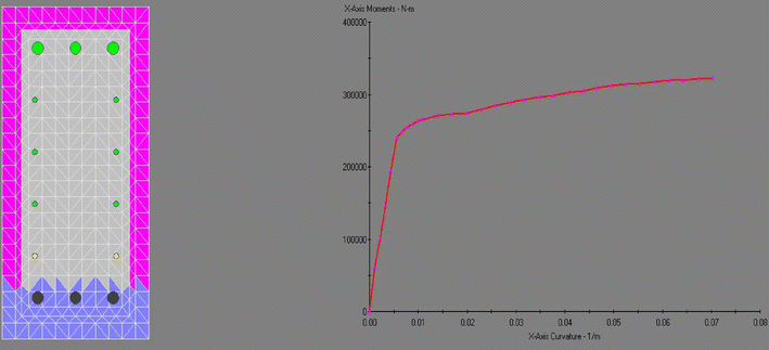
$$ M_{n} = A_{s} \times f_{y} \times \left( {d - \frac{a}{2}} \right) = (1174) \times 400 \times \left( {526.2 - \frac{76.73}{2}} \right) \times 10^{ - 6} = 229.09\,{\text{kN}}\,{\text{m}} $$$$ a = \frac{1174 \times 400}{0.85 \times 24 \times 300} = 76.73\,{\text{mm}} $$$$ C = 0.85 \times f_{ck} \times a \times b = 0.85 \times 24 \times 76.73 \times 300 \times 10^{ - 3} = 469.59\,{\text{kN}} $$$$ F_{BD} = \frac{469.59}{\cos (41.01)} = 622.31\,{\text{kN}} $$$$ F_{BE} = 622.31 \times \sin (41.01) = 408.35\,{\text{kN}} $$$$ F_{EF} = 622.31 \times \cos (41.01) = 469.59\,{\text{kN}} $$For specimens B-1-H, B-2 and B-2-H that all of the horizontal bars of beam (6-HD22 + 8-HD10) are anchored in wall, M n is achieved from a sectional analysis (using Structural Analysis Program XTRACT) (Chadwell 2004) as shown in below. The forces of struts and ties are can be calculated by same process by using the M n .
-
(2)
When stirrup (2-(HD13+HD10)@100) reaches its yield strength due to shear force,
$$ V_{n} = n \times A_{st} \times f_{y} = \frac{9}{2} \times (2 \times 126.7 + 2 \times 71.33) \times 400 \times 10^{ - 3} = 712.91\,{\text{kN}} $$$$ F_{BD} = \frac{712.91}{\sin (41.01)} = 1086.44\,{\text{kN}} $$$$ F_{EF} = \frac{712.91}{\tan (41.01)} = 819.82\,{\text{kN}} $$
-
(1)

Therefore, it is expected that the behavior of the specimen will be governed by bending moment.
Rights and permissions
Open Access This article is distributed under the terms of the Creative Commons Attribution 4.0 International License (http://creativecommons.org/licenses/by/4.0/), which permits unrestricted use, distribution, and reproduction in any medium, provided you give appropriate credit to the original author(s) and the source, provide a link to the Creative Commons license, and indicate if changes were made.
About this article

Cite this article
Seo, SY., Yun, HD. & Chun, YS. Hysteretic Behavior of Conventionally Reinforced Concrete Coupling Beams in Reinforced Concrete Coupled Shear Wall. Int J Concr Struct Mater 11, 599–616 (2017). https://doi.org/10.1007/s40069-017-0221-8
Received:
Accepted:
Published:
Issue Date:
DOI: https://doi.org/10.1007/s40069-017-0221-8