- Research
- Open access
- Published:
Behavior of Small-Scale Concrete Cylinders in Compression Laterally Confined by Basalt Fiber and PEN Fiber Reinforced Polymer Composites
International Journal of Concrete Structures and Materials volume 14, Article number: 8 (2020)
Abstract
Axial compression test was conducted to investigate the effect of confinement on plain concrete cylinders by wrapping polyethylene naphthalate fiber reinforced polymer (PEN FRP) with large rupture strain (LRS) capacity. To draw comparison on the confinement effect by PEN FRP wrapping, the confining effect by basalt FRP (BFRP) wrapping was also investigated. A total of 25 tests was completed. Test variables were two different FRP composites (PEN FRP, BFRP) and number of FRP layers (1, 2, 3 layers of PEN FRP and 2, 4, 6 layers of BFRP) in the main confinement tests (21 tests). In the additional confinement tests, the test variable was overlap length of PEN FRP (four tests). Confinement by BFRP and LRS PEN FRP was both effective as demonstrated by continuously ascending stress–strain relationship of the confined concrete. The PEN FRP wrapped concrete deformed more both axially and laterally to develop strength equivalent to that of the BFRP wrapped concrete. A simplified procedure for rational modelling of stress–strain relationship of the confined concrete was suggested. The suggested procedure is applicable for both BFRP and PEN FRP confined circular concretes on condition that basic confinement test data specific to the FRP composite are provided.
1 Introduction
The confinement effect on concrete by fiber reinforced polymers (FRP) such as carbon FRP (CFRP), glass FRP (GFRP), and aramid FRP (AFRP) has been investigated since o/a 1980 (Kurt 1978; Fardis and Khalili 1981). Many researchers concentrated on the effect of confinement and the modelling of the stress–strain behaviour of the FRP-confined concrete using concrete cylinders and prismatic specimens with square and rectangular cross sections. FRP wrapping can be used for the external confinement of RC columns when the existing transverse reinforcement detail is not proper or poor. FRP provides a concrete column under compression with a triaxial stress state. The confined concrete fails at a larger axial strain than that of the unconfined concrete. At the same time, the lateral pressure provided by the FRP increases the compressive strength of concrete. As a result, enhanced stress–strain behavior of the confined concrete is achieved.
Recent advances of polymer engineering provide broad range of fibers with different engineering properties, and possible application of the new fibers other than carbon fiber, glass fiber, and aramid fiber (hereinafter called “more conventional fibers”) in civil engineering discipline are drawing attention. During the last decade, a new class of fibers with large rupture strain (LRS) capacity such as polyethylene terephthalate (PET) fiber and polyethylene naphthalate (PEN) fiber with about 4.5–15% ultimate rupture strain has emerged, while more conventional fibers typically have 1–3% ultimate rupture strain (Anggawidjaja et al. 2006; Dai et al. 2012; Choi et al. 2015; Zhang et al. 2017). For example, thin bi-axial PET fiber sheet is often used as geotextile fabric. PET fiber has very low elastic modulus (about 1/20th of steel), good tensile strength at relatively large strain, and ultimate tensile strain of about 15%. PEN fiber has higher elastic modulus than PET fiber, good tensile strength, and ultimate strain of about 8%. Both PET and PEN fibers have nonlinear stress–strain relationship.
In this study, PEN FRP was used to confine plain concrete cylinders to investigate the effect of confinement. The PEN FRP was chosen over the PET FRP as preliminary investigation showed that the PEN fiber is more durable than the PET fiber especially in wet and alkaline environment. To draw comparison on the effect of confinement on concrete by LRS PEN FRP, basalt fiber reinforced polymer (BFRP) was chosen because of relatively few existing research on the confinement effect by BFRP.
Basalt fiber, which is also relatively new to civil engineering application, is produced from basalt rocks and has chemical composition and material properties similar to those of glass fiber (Prasad and Talupula 2018). Basalt fiber has excellent thermal resistance such that it can be used as insulating material replacing asbestos which poses health hazards by damaging respiratory systems (Singha 2012). Basalt fiber shows linear-elastic stress–strain behavior. Table 1 summaries physical properties of various fibers often used in civil engineering. The stress–strain plots of the various fibers determined by authors are shown in Fig. 1.

Stress-strain relationship of various fibers.
2 Research Background and Objectives
During the last decade, several researchers have performed research using PET FRP and/or PEN FRP for the purpose of concrete confinement. Dai et al. (2011) investigated the behavior of 42 FRP wrapped concrete cylinders, that consisted of 36 AFRP, PET FRP or PEN FRP confined concrete cylinders and six control cylinders. Test variables were different fibers (AFRP, PET FRP, PEN FRP) and number of FRP layers (1, 2, 3 plies). Under compressive loading, all AFRP-confined specimens failed by tensile rupture of AFRP jacket because of hoop tension at about 3% strain. All PEN FRP confined specimens failed also by tensile rupture of PEN FRP jacket at larger hoop tensile strain over 4%. PET FRP-confined specimens either failed by delamination between plies or hoop tensile rupture of PET FRP. They have concluded that both PET FRP and PEN FRP can enhance the ductility of the LRS FRP-confined concrete substantially because of large rupture strain with a smaller increase in compressive strength compared with conventional FRP. They also proposed an analytical model for the stress–strain behavior of LRS FRP-confined cylindrical specimens based on the existing model by Jiang and Teng (2007).
Saleem et al. (2018) tested a total of 54 prismatic specimens that consisted of circular, square, and rectangular cross sections wrapped by PET FRP. Test variables were number of PET layers (1, 2, 3 layers) and corner radius of square or rectangular cross sections. Axial stress-lateral strain response of PET FRP-confined circular specimens was bilinear with a transition zone between the two almost straight segments, while it was trilinear in case of square and rectangular specimens. They observed that the lateral strain-axial strain response of PET FRP-confined circular specimens is not well predicted by existing models.
BF wrapping on concrete also has been studied recently (Ludovico et al. 2010; Campione et al. 2015; Sadeghian and Fillmore 2018; Ma et al. 2018). Ludovico et al. (2010) used bidirectional basalt laminates preimpregnated with epoxy resin or latex and then bonded with a cement-based mortar (BRM) to confine 23 concrete cylindrical specimens. The BRM confining system could provide a substantial gain both in compressive strength and ductility of concrete members.
Campione et al. (2015) studied the behavior of concrete cylinders externally wrapped by basalt fiber under both monotonic and cyclic compression. Due to very thin bi-axially woven BF sheet used by the authors, the specimens confined with one or two layers of BF showed strain softening behavior with small increases in resistance and a significant increase in ultimate strain. The specimens confined with three layers of BF showed temporary softening right after the peak followed by a plastic-like stabilized stress–strain behavior. They concluded that BFRP confinement was able to stabilize post-peak behavior of extensively cracked concrete even for low confinement ratio.
Sadeghian and Fillmore (2018) used unidirectional BF to test twelve cylinders wrapped with 2, 4, 6 layers of BFRP. Wrapping the plain concrete cylinders with 2, 4, 6 layers of BFRP increased the strength with a factor of 1.41, 1.92, and 2.36, respectively. They especially investigated the distribution of hoop strains using six strain gauges at mid-height of the cylinder under axial compression. Difference of hoop strains between the overlap and the non-overlap regions was not significant and the average strain could represent the overall dilation of the specimens.
From above, it is understood that Dai et al. (2011) first presented the behavior and the numerical modeling of concrete cylinders confined by LRS PEN/PET FRP while Saleem et al. (2018) concentrated on comparison of the stress–strain behaviors of the prismatic specimens with circular, square, and rectangular cross sections confined by PET FRP. Saleem et al. also compared the predictions of lateral strain-axial strain response by existing models with the experimental results of PET FRP-confined circular specimens. They, after comparison of the existing models and their test data, concluded that the existing models were unable to predict well the lateral strain-axial strain response of PET FRP-confined circular specimens. The model by Dai et al. provided good prediction in case of moderately confined specimen, but underestimated the lateral strains in case of more heavily confined specimens (by Dai et al., the axial-to-lateral strain relationship in the existing model by Jiang and Teng (2007) was modified as it was originally proposed based on the test results of concrete confined with conventional FRPs). Saleem et al. suggested that further refinement in the lateral strain-axial strain relationship is needed. There is a clear need for additional research that expands data on the behavior of concretes confined by LRS PEN FRP to facilitate the application of this new class of LRS fiber. In addition, although many analytical modeling methods have been suggested, there is a need for refinement especially for the application of LRS FRP.
The objectives of this research are as follows:
Expand test data on confinement effect of low to normal strength concrete by LRS PEN FRP as well as by BFRP;
Compare and identify the differences, if any, in the behavior of the concretes confined by LRS PEN FRP and more conventional BFRP including stress–strain relationship, failure mode, and effectiveness of fibers;
Investigate the overlap length of LRS PEN FRP; and
Suggest a simplified modeling method of FRP-confined concrete.
Use of LRS FRP can be effective for the seismic strengthening of RC structures and members as it demonstrates significant ductility and energy absorption capacity. It is shown in this paper that the current simplified design oriented modeling approach gives a good prediction of stress–strain relationship of concretes confined by LRS PEN FRP as well as more conventional BFRP. The varying overlap lengths have been tested in an attempt to suggest a proper length for the LRS PEN FRP. It is also noted that the FRP efficiency factor has been often reported as a fixed value specific per fiber type. It will be shown that the FRP efficiency factor may vary for the LRS FRP depending on the level of lateral confinement and the failure mode such as debonding failure.
3 Material Properties and Test Preparation
3.1 Fibers and Adhesive
Inorganic basalt continuous filaments are produced from basalt rocks by melting and extrusion process similar to that of glass fiber filaments. The physical properties of BF vary depending on the source rock as mineral level and chemical composition can differ significantly from one location to another (Singha 2012). On the other hand, synthetic PEN fiber is a thermoplastic polymer of the polyester family. Figure 2 shows a spool of BF roving and a roll of uniaxial PEN fiber sheet used in this study.

BF and PEN fiber
The material properties in tension of BF roving, PEN fiber roving, PEN fiber sheet, and PEN FRP (PEN fiber sheet + adhesive) were measured. Tensile tests of BF and PEN fibers were performed following ISO 10406-2 (2015). In Table 2, the thickness of BF roving and PEN fiber roving was determined from the cross-sectional area and the width of each fiber roving.
The nominal cross-sectional area was determined using density provided by the manufacturer and Eq. (1):
where A—cross-sectional area, mm2; w—weight of test specimen, g; ρ—density, g/mm3; l—length, mm.
The mechanical properties of a two-part epoxy (adhesive) used in this study in tension were determined following ASTM D638 (2008). The tensile properties of BF, PEN fiber, and adhesive are summarized in Table 3. Figure 3 shows stress–strain relationship of BF and PEN fiber. In Table 3 and Fig. 3a BF roving has linear-elastic stress–strain behavior with tensile strength of 1226 MPa, ultimate rupture strain of 1.95% in tension, and elastic modulus of 68.4 GPa. PEN fiber roving has nonlinear stress–strain relationship with strength of 822 MPa and about 8% ultimate strain with a secant elastic modulus of 17.4 GPa up to 1% strain: i.e. the elastic modulus of PEN fiber is low (only about 1/4th of BF). The nonlinear stress–strain behavior of PEN fiber was modeled using a bilinear relationship as shown in Fig. 3b where the first line connects the origin and the stress at 1% fiber strain. The bilinear relationship shown in Table 3 and Fig. 3b was later used for modeling stress–strain behavior of concretes confined by PEN FRP (see clause 4.2).

Stress-strain relationship of BF and PEN fiber.
3.2 Preparation for Confinement Test
3.2.1 Concrete Cylinders Used for Main Confinement Test and Additional Confinement Test
To investigate the effect of confinement by BFRP- and LRS PEN FRP-wrapping, 21 concrete cylinders with 150-mm diameter and 300-mm height were prepared and tested including three Control cylinders, nine BFRP wrapped cylinders, and nine PEN FRP wrapped cylinders in the main confinement test program as summarized in Table 4. Concrete with 20-mm nominal size crushed coarse aggregate and 150-mm slump was cast using plastic cylinder molds. All specimens were demolded after one day and cured under water (T = 20 ± 3 °C). After 28-day wet cure, top surface of the specimen was lightly ground to make even surface for compressive testing. The 28-day compressive strength of three replicate cylinders was 23.5 MPa (average of three test results with a standard deviation of 0.16 MPa).
One of the objectives of this study was to investigate the overlap length of LRS PEN FRP. After completion of the main confinement tests, four additional confinement tests were conducted as shown in Table 4 to evaluate the effect of different overlap lengths using concrete cylinders wrapped by two layers of PEN FRP. Test methods were the same as the main confinement test except for the compressive strength of the control concrete.
3.2.2 Fiber Wrapping
A total of four electronic strain gages of 60-mm length (a set of two vertical strain gauges at 180° angle and another set of two horizontal strain gauges at 180° angle, respectively) were bonded on a concrete cylinder before fiber wrapping at mid-height as shown in Fig. 4a. Test variables were two different FRPs (BFRP, PEN FRP) and number of FRP layers (2, 4, 6 layers of BFRP and 1, 2, 3 layers of PEN FRP) in the main confinement test. The stiffness of confinement by PEN fiber sheet 1, 2, and 3 layers is similar to that by BF 2, 4, and 6 layers, respectively, as shown in Table 5, where the stiffness of confinement El is defined by Eq. (2) as a function of fiber elastic modulus, fiber thickness, and diameter of the concrete cylinder:

Concrete cylinder types.
where Ef—modulus of elasticity of the fiber; tf—thickness of fiber; D—diameter of concrete cylinder.
The fiber volume ratio for specimens confined by BF 2, 4, and 6 layers is 0.60%, 1.21%, and 1.81%, while that of specimens confined by PEN 1, 2, and 3 layers is 2.25%, 4.5%, and 6.74%, respectively, in Table 5. Adhesive amount of 100% and 200% by fiber volume was applied on the PEN fiber sheet and the BF rovings, respectively. From the fiber volume ratio, it can be seen that the PEN FRP wrapping is thick (e.g. One layer of PEN FRP is about 2 mm thick). In Table 5, Ef for the PEN FRP is used rather than that of the PEN fiber sheet because the amount of adhesive used for the PEN FRP is substantial due to high fiber volume and so the effect of the adhesive needs to be included.
Uniaxial PEN fiber sheet and BF rovings were cut in predetermined lengths. Small amount of adhesive was first applied on concrete cylinder surface prior to fiber wrapping to fill micro voids on the surface and also to improve bond between concrete and fibers. Concrete cylinders were then manually rolled up on the PEN fiber sheet or BF rovings placed on horizontal flat surface in wet layup without any introduction of pretension force. Whole height of a cylinder was wrapped except 10-mm length at top and bottom ends of a cylinder, respectively.
All BFRP wraps had 50-mm overlap length based on bond test results by one of the authors (Baasankhuu 2019). The overlap length varied for PEN FRP wrapping: the overlap length for PEN fiber sheet 1 layer was 150 mm (about 1/3rd of the perimeter), 50 mm for 2 layers, and nil for 3 layers. The effect of the varying overlap lengths for the PEN FRP confinement was evaluated by additional confinement test, which was performed after completion of the main confinement test.
3.2.3 Procedure of Confinement Test
Pure axial compression test was performed after 7 days of adhesive hardening. A set of three linear variable displacement transducers (LVDTs) with 50-mm gauge length vertically mounted on a special compressometer was used to measure axial displacements. In addition, another set of three 50-mm LVDTs mounted horizontally on the compressometer was used to measure dispacements in the radial direction on concrete surface for the Control specimens and on FRP in case of the FRP wrapped specimens. The LVDTs were at 120° angle with each other both horizontally and vertically as shown in Fig. 5. 1200-kN capacity universal testing machine (UTM) was operated in displacement control at a ramp rate of 0.6 mm/min. A data logger connected to computer was used for electronic data retrieval and storage while the data acquisition rate was one data set per five seconds.

Compression test under progress.
4 Confinement Test Results
4.1 Results of Main Confinement Test
Both BFRP and PEN FRP were effective to increase axial strength, axial strain as well as lateral strain (or hoop strain) of the FRP-confined concrete over the unconfined concrete in all confinement tests. Axial load data were retrieved from load cell of the UTM while the LVDTs and the strain gauges provided displacement and strain data, respectively. The vertical LVDT readings were converted to axial strains taking into account the LVDT gauge length. The horizontal LVDT readings (displacements in the radial direction) were converted to hoop strains using principles of the mechanics of materials. At the same axial load level, the strain readings from LVDTs were in general a little larger than those from strain gauges. For the interpretation of the test results, the strain gauge reading were given priority and used as much as possible. At large strain values, however, data from LVDTs were also heavily utilized especially for the confinement by LRS PEN FRP wrapping.
4.1.1 Stress–Strain Behavior of Confined Concrete
The confinement test results are summarized in Table 6 and also shown in Fig. 6 in terms of axial load versus axial/hoop strain plots for BFRP- and PEN FRP-confined specimens as well as Control specimens. It can be seen that all BFRP and PEN FRP wrapping schemes adopted in this study provided “sufficient confinement” (or “hardening”) as demonstrated by continuously increasing strengths with increasing axial and/or hoop strains in Fig. 6 (ACI 440.2 2017).

Axial stress-axial/hoop strain plot of BFRP and PEN FRP confined concretes.
In Table 6, the confinement by BFRP 2, 4, 6 layers results in 35.2–62.5 MPa axial strength while that of unconfined concrete is 24.8 MPa (average of three tests). The confinement by PEN FRP 1, 2, 3 layers results in 33.9–62.6 MPa axial strength of the confined concretes (average of three tests). The maximum axial strain is 0.021–0.032 m/m for BFRP wrapping and it is 0.033–0.056 m/m for PEN FRP wrapping. The maximum hoop strain for BFRP wrapping is 0.02–0.021 m/m and it is 0.034–0.053 m/m for PEN FRP wrapping.
Test results show that similar strength of the confined concretes was attained by BFRP or PEN FRP wrapping with similar stiffness of confinement El: i.e. El is 206–618 MPa for BFRP and it is 239–719 MPa for PEN FRP in Table 5. The axial strength of concrete confined by the PEN FRP was achieved at much higher axial/hoop strains of the confined concrete than the BFRP wrapping (or PEN FRP wrapped concrete deformed more laterally to develop axial strength equivalent to that of BFRP wrapped concrete). All BFRP wrapped specimens failed by rupture of BFRP in tension at about 2% hoop strain. All PEN FRP wrapped specimens failed by delamination between FRP layers or delamination followed by FRP rupture in tension at about 3.5–6% hoop strain (average of three tests). The maximum hoop strain was typically much smaller than the PEN FRP’s ultimate rupture strain of about 9% in tension due to FRP debonding (see Table 3).
4.1.2 Strength Enhancement
It is well known that the strength improvement of confined concrete can be expressed by Eq. (3) according to early work by Richart et al. (1928):
where \(f'_{cc}\) is maximum stress of confined concrete, \(f'_{co}\) is maximum stress of unconfined concrete, \(k_{1}\) is a coefficient used to express strength enhancement by confinement, and \(f_{l}\) is lateral confining pressure provided by FRP.
The lateral confining pressure in Eq. (3) can be determined by Eq. (4):
where \(f_{f}\) is stress of FRP at maximum load, \(t_{f}\) is thickness of FRP, and D is diameter of concrete cylinder.
In case of BFRP with linearly-elastic stress–strain behavior, Eq. (4) becomes Eq. (5):
where \(E_{f}\) is elastic modulus of FRP and \(\varepsilon_{f}\) is effective strain of FRP at fiber rupture.
In case of FRP with non-linear stress–strain relationship such as PEN FRP, ff (stress passively developed in the FRP by lateral expansion of concrete subjected to axial compression) can be determined according to constitutive relationship of the specific FRP (see Fig. 3b). Based on nine test data on BFRP and PEN FRP, respectively, linear regression analyses were performed to determine \(k_{1}\) using Eqs. (3) through (5) with results shown in Fig. 7. Figure 7 shows that \(k_{1}\) = 2.88 for BFRP with coefficient of determination R2 = 0.93 and \(k_{1}\) = 1.80 for PEN FRP with R2 = 0.90. \(k_{1}\) of PEN FRP is smaller than that of BFRP because of low elastic modulus of LRS PEN FRP.

Linear regression for k1.
4.1.3 Strain Enhancement and Ultimate Poisson’s Ratio
Wu et al. (2006) suggested that the ultimate Poisson’s Ratio (defined as the ratio of lateral strain over axial strain at the maximum load in confined and cracked concrete) of sufficiently confined concrete tends to an asymptotic value and the ultimate strain of FRP-confined concrete could be predicted through calculation of the ultimate Poisson’s Ratio as shown in Fig. 8. In Fig. 8, Sa-1 is unconfined concrete, Sa-2 is concrete confined with high-elastic modulus CFRP, while Sa-3, -4, -5 are concretes confined by CFRP, GFRP, and AFRP, respectively. It is clear that, in each experiment, the Poisson’s Ratio converges to an asymptotic value at the peak for the confined concrete.

Relationship of axial stress and Poisson’s Ratio of FRP-confined concrete (Wu et al. 2006).
Figure 9 shows test results in this study which show that, with increasing lateral confining pressure fl, the ultimate Poisson’s Ratio ν tends to decrease. In Fig. 9, for BFRP that has high elastic modulus, the ultimate Poisson’s Ratio is sensitive to lateral pressure such that the ultimate Poisson’s Ratio decreases rapidly with increasing lateral pressure. On the other hand, for PEN FRP that has low elastic modulus, the ultimate Poisson’s Ratio tends to decrease with increasing lateral confining pressure. The curve-fit shows an exponential function for the BFRP and a linear equation for PEN FRP. The ultimate Poisson’s Ratio of confined concretes is between 0.6 and 1.2 for BFRP wrapping, and it is between 0.8 and 1.2 for PEN FRP wrapping.

Relationship of confinement pressure and ultimate Poisson’s Ratio at maximum load.
As shown in Fig. 9, the ultimate Poisson’s Ratio ν decreases with increasing lateral confining pressure fl, while fl increases with increasing elastic modulus and effective strain of FRP at rupture in Eq. (5). The current results show that the stiffness of FRP as well as ductility of FRP (effective rupture strain) affect the ultimate Poisson’s Ratio significantly: i.e. both stiffness and ductility of FRP influences the ultimate axial/lateral strain of the confined concrete. This is an observation in line with results of existing research (Lam and Teng 2003; Lorenzis and Tepfers 2003; Teng et al. 2009).
The relationship between axial strain \(\varepsilon_{cc}\), lateral strain \(\varepsilon_{l}\), and the Poisson’s Ratio \(\nu\) at maximum stress is expressed by Eqs. (6) and (7) for BFRP- and PEN FRP-confined concretes, respectively, using results of the regression analyses shown in Fig. 9.
where \(\nu\) is ultimate Poisson’s Ratio, \(f_{l}\) is confinement pressure, \(\varepsilon_{l}\) is hoop strain, and \(\varepsilon_{cc}\) is axial strain at maximum load.
4.2 Simplified Modeling for Stress–Strain Relationship
Many researchers proposed a theoretical model which can be categorized as design oriented model (Nanni and Bradford 1995; Toutanji 1999; Xiao and Wu 2000; Lam and Teng 2003; Lorenzis and Tepfers 2003; Teng et al. 2009; Pham et al. 2013; Wu et al. 2006) and analysis oriented model (Jiang and Teng 2007; Mirmiran and Shahawy 1997; Spoelstra and Monti 1999; Karabinis and Rousakis 2002; Becque et al. 2003; Binici 2005; Pellegrino and Modena 2010; Cascardi et al. 2017). Toutanji (1999) proposed a design-oriented model that consists of two distinctive regions (or two curves). In the first curve, the stress–strain relationship is similar to that of plain concrete since lateral expansion of concrete is small. In the second curve, as the FRP wrap is fully activated, the stiffness is stabilized around a constant rate. Xiao and Wu (2000) suggested a bilinear model. Lam and Teng (2003) proposed a model where the first part is Hognestad parabola and the second part is a straight line. However, Saleem et al. (2018) observed that the lateral strain-axial strain response of PET FRP-confined circular specimens is not well predicted by existing models. Dai et al. (2011) proposed a modified analytical model for the stress–strain behavior of LRS FRP-confined cylindrical specimens based on existing model by Jiang and Teng (2007).
In this study, a simplified construction of the stress–strain relationship of sufficiently confined concrete is attempted using k1, Eqs. (3) through (5), and axial stress-Poisson’s Ratio relationship shown in Figs. 9 and 10. In the current approach of simplified modeling which consists of one curve and one straight line, the first curve can be modeled as suggested by Ahmad and Shah (1982). The construction of the first curve has been described elsewhere (Toutanji 1999; Ahmad and Shah 1982). It is assumed that the first curve and the second straight line meet at an axial strain of 0.0020 (instead of 0.0021 determined from test) for simplicity (ACI 440.2 2017; Mander et al. 1988; Nanni and Bradford 1995). The second and straight line can be defined by following steps described below:

Relationship of axial stress and Poisson’s Ratio: test results.
-
1.
On positive x-axis of the stress–strain plot, εc1 = 0.0020 (same as εco) is first located (see Fig. 11a).
Fig. 11 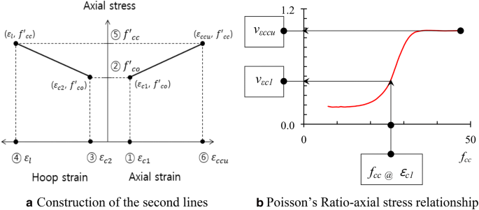
Construction of simplified stress–strain model.
-
2.
On y-axis, fcc corresponding to εc1 is the same as f′co (Alternatively, fcc can be more. accurately determined from test data as shown in Fig. 14).
-
3.
Using axial stress-Poisson’s Ratio relationship, εc2 corresponding to εc1 is located along negative x-axis: εc2 = εc1 x\(\nu_{\varepsilon c1 }\): x = fcc @ εc1 and y = \(\nu_{\varepsilon c1 }\) in Fig. 11(b).
-
4.
On negative x-axis, εl= εh,rup : εh,rup = εf,rup x FRP efficiency factor: εf,rup is rupture strain of fiber determined from tensile coupon test in Table 3; see clause 5.3 for the FRP efficiency factor.
-
5.
On y-axis, f′cc is determined using Eqs. (3) and (4) and the strength enhancement factor k1: see clause 4.1.2 for strength enhancement factor.
-
6.
On positive x-axis, εccu is determined by dividing εl by \(\nu_{\varepsilon ccu}\) while \(\nu_{\varepsilon ccu}\) is asymptotic value of ν (or ultimate Poisson’s Ratio) in Fig. 11b.

The stress–strain relationship modeled using the current procedure is plotted with test data for BFRP- and PEN FRP-confined concretes in Fig. 12. By using the current approach, modeling of the stress–strain relationship of concretes confined by more conventional BFRP and LRS PEN FRP is both possible. It is noted that the first and curved portion of the model shown in Fig. 12 is constructed using work by Ahmad and Shah (1982) considering boundary conditions at the origin and at the transition of the first curve and the second straight line.

Test data vs. stress–strain model.
4.3 Results of Additional Confinement Test
Four additional confinement tests were performed after completion of the main confinement tests: one Control cylinder and three PEN FRP wrapped cylinders using two layers of PEN FRP. Test variable was different overlap lengths (nil, 50 mm, and 150 mm) to observe the changes in the behavior of the confined concretes with different overlap lengths. Table 7 summarizes the test results. Figure 13 shows the axial stress-axial/hoop strain plots determined from test. Table 7 and Fig. 13 show that, as the overlap length changes, the stress–strain behavior of the confined concrete changes. Axial strength of C-P2-150 mm is 60 kN while that of both C-P2-0 mm and C-P2-50 mm is 53 kN: i.e. the axial strength is reduced by about 13% for C-P2-0 mm and C-P2-50 mm from that of C-P2-150 mm. The measured maximum hoop strains are almost the same in Fig. 13, but the axial strain of C-P2-0 mm is smaller than that of C-P2-150 mm.

Stress-strain relationship: additional confinement test.
5 Discussion on Confinement Test Results and Validation of Suggested Model
5.1 f′ co and f cc at ε co
For unconfined concrete, εco = 0.0021 and f′co = 24.8 MPa on average from the test results in Table 6 and Fig. 6. Test results shown in Fig. 14 show that the ratio of fcc @ εco over f′co ranges between 1.0 and 1.2 for the BFRP wrapping, while the ratio ranges between 0.85 and 1.13 for the PEN FRP wrapping. It is understood that fcc @ εco is higher than f′co for BFRP-confined concretes, while fcc @ εco is about the same as f′co (or increase slowly with increasing fl) for PEN FRP-confined concretes due to low elastic modulus of LRS PEN FRP: i.e. the lateral confining pressure fl is relatively small at εco because of low elastic modulus of LRS PEN FRP.

Relationship of confinement pressure and strength of confined concrete at εco.
5.2 Failure Mode and Overlap Length
All BFRP wrapped specimens had 50-mm overlap length. As all BFRP wrapped specimens failed by rupture of BFRP in hoop tension outside the overlap region, it can be construed that the 50-mm overlap adopted provided the overlap length needed for the thin BFRP used in this study. On the other hand, three different failure modes were observed from the concrete cylinders confined by PEN FRP: (1) delamination failure; (2) failure by delamination and rupture; and (3) FRP rupture. Most PEN FRP-confined specimens showed delamination failure between FRP layers. In the delamination failure, local debonding between layers of PEN FRP typically started within mid 2/3rd portion of the vertical joint and the initial localized debonding slowly spread along the vertical joint. Close to the maximum load, a horizontal strip of PEN fiber sheet was sheared off by cutting through weft of the fiber sheet at top and bottom of the strip, which led to a delamination failure as shown in Fig. 15c. In Tables 6 and 7, two specimens (C-P2-2, 3) in the main confinement test and a specimen in the additional confinement test (C-P2-50 mm; see Fig. 16b) failed by delamination followed by sudden FRP rupture: i.e. failure by delamination and rupture. In addition, two PEN FRP wrapped specimens (C-P2-0 mm and C-P2-150 mm) failed by sudden rupture of PEN FRP at the mid-height of the cylinder as shown in Fig. 16a and Table 7.

Failure mode of Control and BFRP- and PEN FRP-confined cylinders: main confinement tests.

Failure mode of PEN FRP-confined cylinders: additional confinement tests.
Dai et al. (2011) used overlap length of at least 150 mm for the PEN FRP wrapping. They reported that all PEN FRP jackets failed by hoop tensile rupture of the FRP jacket at about 4.5% hoop strain. Based on observations on the stress–strain behaviors and the failure modes determined in this study as well as existing test results by Dai et al. (2011), it can be suggested that the proper overlap length for the PEN FRP is at least 150 mm.
5.3 Hoop Rupture Strain and FRP Efficiency Factor
The FRP efficiency factor (FEF) is defined as the ratio of the hoop rupture strain of FRP during compression test of the confined concrete over the rupture strain of FRP determined by tensile coupon test (εh,rup/εf,rup). FEF is often smaller than unity (ACI 440.2 2017).
In Fig. 17a, εh,rup/εf,rup ratios determined from test are shown for the BFRP wrapping, where the ratios range between 0.92 and 1.20 with an average of 1.04. A solid horizontal line shows the average value in Fig. 17a. By downward translation of the solid line, a new dashed can be defined such that the dashed line represents the 95% fractile of the test data by εh,rup/εf,rup = 0.896. For simplicity, FEF of 0.89 can be finally suggested for the BFRP wrapping. It is noted that the current suggestion also agrees with result of an existing study: e.g. Suon et al. (2019) suggested the hoop strain efficiency factor of 0.88 for 12 circular specimens confined by 3, 6, and 9 layers of BFRP sheet.

FRP rupture strain: test results.
In Fig. 17b, εh,rup/εf,rup ratios determined from test are shown for the PEN FRP wrapping, where the ratios range between 0.34 and 0.73 with an average of 0.45 (including both main and additional confinement tests). εh,rup/εf,rup ratio increases with increasing fl/f′co in Fig. 17b. By regression analysis, a linear equation (solid line) is determined with coefficient of determination R2 = 0.83. Again, a dashed line can be defined which satisfies 95% fractile of the test data as shown in Eq. (8). Equation (8) clearly indicates that the FEF increases with increasing lateral stiffness for PEN FRP.
where fl is lateral confining pressure and f′co is maximum stress of unconfined concrete.
It is noted that the hoop rupture strains of PEN FRP determined in this study are similar to those reported by Dai et al. (2011). The hoop rupture strains in this study range between 3.1% and 6.7% with an average value of 4.2% in Table 6, while Dai et al. (2011) reported that the average hoop rupture strain was 4.5% while it ranged between 3.6% and 5.2% in their confinement study of normal strength concretes confined using 1, 2, 3 layers of PEN FRP.
5.4 Validation of Suggested Model in View of Merged Test Data
In this study, a simplified approach for rational modeling of the stress–strain behavior of FRP-confined concrete has been proposed, which is applicable both to more conventional fiber based FRP composite and LRS FRP composite. Dai et al. (2011) and Saleem et al. (2018) have published test results of concrete cylinders confined by AFRP and LRS PET and PEN FRP, which provide a total of 39 test data: 36 tests by Dai et al. and three tests by Saleem et al. Authors have tested 21 concrete cylinders confined by BFRP or LRS PEN FRP. So a total of 60 test data has been collected. The strength enhancement factor k1 was reevaluated by regression analysis of the merged data as shown in Fig. 18a, where k1 = 2.45 for the merged data with R2 = 0.79. Using Eq. (3) and k1 = 2.45, the axial strength was calculated and compared with the test data with results shown in Fig. 19a. Figure 18b shows results of another regression analysis for the relationship between the ultimate Poisson’s Ratio and lateral pressure for the merged data. Using Eq. (9) and rupture strain from tests (εh,rup in Tables 6, 7, and 8), the ultimate axial strain was calculated and compared with the merged data with results shown in Fig. 19b. Figure 19a shows that almost all data falls between the ± 20% margin of error. In Fig. 19b, it is understood that the axial strain is not as well predicted as the axial strength.


It is noted that, to construct a simplified stress–strain relationship, the minimum requirement is a set of basic test data for control and confined concretes because such data are needed to determine the strength enhancement factor k1 and the ultimate Poisson’s Ratio ν specific to the fiber type. In addition, the suggested procedure is only applicable to sufficiently confined cylindrical concrete (i.e. heavily confined-hardening, ACI 440.2 2017).
6 Conclusions
Stress–strain relationship of plain concrete cylinders confined by PEN FRP composite was investigated using low to normal strength concretes. To draw comparison on the behaviour of concrete confined by LRS PEN FRP, behaviour of concrete confined by BFRP was also investigated. Results of current work demonstrate that both BFRP- and LRS PEN FRP-wrapping are efficient method for strengthening concrete columns. Findings of this study are as follows:
- 1.
Similar improved strengths could be attained from plain concrete cylinders confined by 2, 4, 6 layers of BFRP wrapping or 1, 2, 3 layers of PEN FRP wrapping with similar stiffness of confinement El (El = 206–618 MPa for BFRP wrapping; El = 239–719 MPa for PEN FRP wrapping). The compressive strength of confined concrete by BFRP 2-6 layers/PEN FRP 1–3 layers was 1.4–2.5 times that of the unconfined concrete.
- 2.
The strength of concrete wrapped by PEN FRP was achieved at much higher axial/lateral strain of the confined concrete than the BFRP wrapping: PEN FRP wrapped concrete deformed more laterally to develop axial strength equivalent to BFRP wrapped concrete.
- 3.
Measured maximum axial strain was 2.1%–3.2% for 2–6 layers of BFRP wrapping and 3.3%–5.6% for 1–3 layers of PEN FRP wrapping, respectively (Axial deformation of the PEN FRP confined concrete was about 150%–175% of that of the BFRP confined concrete). The maximum hoop strain was 2.0%–2.1% for 2–6 layers of BFRP wrapping and 3.4%–5.3% for 1–3 layers of PEN FRP wrapping, respectively (lateral deformation of the PEN FRP confined concrete was about 175%–250% of that of the BFRP confined concrete).
- 4.
Strength enhancement factor k1 of 2.88 for BFRP wrapping and 1.80 for PEN FRP wrapping is suggested as a result of regression analyses of the current test data. The k1 is low for LRS PEN FRP because of low elastic modulus.
- 5.
FRP efficiency factor (FEF) of 0.89 is suggested for BFRP wrapping based on current test results. On the other hand FEF varied for the PEN FRP wrapping depending on the lateral pressure. FEF increases from 0.27 for 1 layer of PEN FRP wrapping and 0.51 for three layers of PEN FRP wrapping. As early delamination of LRS PEN FRP that occurs before FRP rupture in tension is responsible for the low FEF of the LRS PEN FRP, an effective method is desired that can arrest the debonding between the LRS FRP layers to improve on the efficiency of the PEN FRP wrapping.
- 6.
Based on current test results, at least 50-mm and 150-mm overlap lengths are suggested for BFRP and PEN FRP wrapping, respectively.
- 7.
The strength enhancement factor k1, ultimate Poisson’s Ratio ν, and FRP efficiency factor were used for simplified modeling of the stress–strain relationship for the confined concrete. The suggested modeling method is applicable to sufficiently confined cylindrical concrete.
It is noted that, since application of the confinement study results is often on RC piers (e.g. seismic strengthening of existing RC piers), the durability properties of the FRP composites exposed to different outdoor exposure conditions are also needed. Such research is under progress by the authors for PEN FRP composites used in this study.
Availability of data and materials
Not applicable.
Abbreviations
- A :
-
cross-sectional area, mm2
- D :
-
diameter of concrete cylinder, mm
- E 1 :
-
secant modulus corresponding to 1% strain of PEN fiber (or PEN FRP), GPa
- E 2 :
-
slope of the second line for PEN fiber (or PEN FRP) used in bilinear model, GPa
- E f :
-
elastic modulus of fiber (or FRP), GPa
- E l :
-
stiffness of confinement, MPa
- f cc :
-
stress developed in confined concrete, MPa
- f′ cc :
-
maximum stress of confined concrete, MPa
- f′ co :
-
maximum stress of unconfined concrete, MPa
- f f :
-
stress of FRP, MPa
- f l :
-
lateral confining pressure provided by FRP, MPa
- k 1 :
-
strength enhancement factor by confinement
- k 2 :
-
strain enhancement factor by confinement
- t f :
-
thickness of fiber (or FRP), mm
- w :
-
weight in g
- ε c1 :
-
axial strain of confined concrete at stress fcc @ εco, m/m (same as εco)
- ε c2 :
-
hoop strain of confined concrete at stress fcc @ εco, m/m
- ε cc :
-
axial strain of confined concrete, m/m
- ε ccu :
-
axial strain of confined concrete at maximum stress, m/m
- ε co :
-
axial strain of unconfined concrete at maximum stress, m/m
- ε l :
-
hoop strain at maximum load used in modelling, m/m
- ε f,rup.:
-
rupture strain of fiber (or FRP) determined by tensile coupon test, m/m
- ε h,rup. :
-
hoop strain of FRP at rupture during confinement test, m/m
- ν:
-
ratio of (-) lateral strain to axial strain (or ratio of maximum lateral strain to maximum axial strain of concrete at ultimate, ultimate Poisson’s Ratio)
- νεc1 :
-
Poisson’s Ratio of confined concrete corresponding to fcc @ εc1 in a Poisson’s Ratio-axial stress relationship, which is provided as test result
- νεccu :
-
ultimate Poisson’s Ratio of confined concrete at ultimate, provided as test result
- ρ:
-
density in g/mm3
References
ACI 440.2-17 (2017) Guide for the design and construction of externally bonded frp systems for strengthening concrete structures. American Concrete Institute, Farmington Hills.
Ahmad, S. H., & Shah, S. P. (1982). Stress-strain curves of concrete confined by spiral reinforcement. ACI Journal Proceedings, 79(6), 484–490.
Anggawidjaja, D., Ueda, T., Dai, J., & Nakai, H. (2006). Deformation capacity of RC piers wrapped by new fiber-reinforced polymer with large fracture strain. Cement & Concrete Composites, 28, 914–927.
ASTM D 638-08 (2008) Standard test method for tensile properties of plastics. American Society of Testing and Materials, West Conshohocken
Baasankhuu, B. (2019). Basic study for seismic strengthening of reinforced concrete (RC) structural members using basalt fiber (BF) and ductile polyethylene naphthalate (PEN). S. degree: Thesis submitted to Hankyong National University in partial fulfilment toward M.
Becque, J., Patnaik, A. K., & Rizkalla, S. H. (2003). Analytical models for concrete confined with frp tubes. ASCE Journal of Composites for Construction, 7(1), 31–38.
Binici, B. (2005). An analytical model for stress-strain behaviour of confined concrete. Engineering Strictures, 27, 1040–1051.
Campione, G., Mendola, L. L., Monaco, A., Valenza, A., & Fiore, V. (2015). Behavior in compression of concrete cylinders externally wrapped with basalt fibers. Composites Part B, 69, 576–586.
Cascardi, A., Micelli, F., & Aiello, M. A. (2017). An artificial neural networks model for the prediction of the compressive strength of FRP-confined concrete circular columns. Engineering Structures, 140, 199–208.
Choi, D., Vachirapanyakun, S., Kim, S.-Y., & Ha, S.-S. (2015). Ductile fiber wrapping for seismic retrofit of reinforced concrete columns. Journal of Asian Concrete Federation, 1(1), 37–46.
Dai, J.-G., Bai, Y.-L., & Teng, J. G. (2011). Behavior and modeling of concrete confined with FRP composites of large deformability. ASCE Journal of Composites for Construction, 15(6), 963–973.
Dai, J., Lam, L., & Ueda, T. (2012). Seismic retrofit of square RC columns with polyethylene terephthalate (PET) fibre reinforced polymer composites. Construction and Building Materials, 27, 206–217.
Fam, A. Z., & Rizkalla, S. H. (2001). Confinement model for axially loaded concrete confined by circular fiber-reinforced polymer tubes. Structural Journal, 98(4), 451–461.
Fardis, M. N., & Khalili, H. (1981). Concrete encased in fiberglass-reinforced plastic. ACI Journal proceedings, 78(6), 440–446.
ISO 10406-2 (2015) Fiber reinforced polymer (FRP) reinforcement of concrete–test methods–Part 2: FRP sheets. International Organization for Standardization, Geneva: Switzerland.
Jiang, T., & Teng, J. G. (2007). Analysis-oriented stress-strain models for FRP-confined concrete. Engineering Structures, 29, 2968–2986.
Karabinis, A. I., & Rousakis, T. C. (2002). Concrete confined by FRP material: A plasticity approach. Engineering Structures, 24, 923–932.
Kurt, C. E. (1978). Concrete filled structural plastic columns. ASCE Journal of Structural Division, 104(1), 55–63.
Lam, L., & Teng, J. G. (2003). Design-oriented stress–strain model for FRP-confined concrete. Construction and Building Materials, 17, 471–489.
Lam, L., & Teng, J. G. (2004). Ultimate condition of fiber reinforced polymer-confined concrete. ASCE Journal of Composites for Construction, 8(6), 539–548.
Lorenzis, L. D., & Tepfers, R. (2003). Comparative study of models on confinement of concrete cylinders with fiber-reinforced polymer composites. ASCE Journal of Composites for Construction, 7(3), 219–237.
Ludovico, M. D., Prota, A., & Manfredi, G. (2010). Structural upgrade using basalt fibers for concrete confinement. ASCE Journal of Composites for Construction, 14(5), 541–552.
Ma, G., Li, H., Yan, L., & Huang, L. (2018). Testing and analysis of basalt FRP-confined damaged concrete cylinders under axial compression loading. Construction and Building Materials, 169, 762–774.
Mander, J., Priestley, J., & Park, R. (1988). Theoretical stress—strain model for confined concrete. Journal of Structural Engineering, 114(8), 1804–1826.
Mirmiran, A., & Shahawy, M. (1997). Behavior of concrete columns confined by fiber composites. ASCE Journal of Structural Engineering, 123(5), 583–590.
Nanni, A., & Bradford, N. M. (1995). FRP jacketed concrete under uniaxial compression. Construction and Building Materials, 9(2), 115–124.
Pellegrino, C., & Modena, C. (2010). Analytical model for frp confinement of concrete columns with and without internal steel reinforcement. ASCE Journal of Composites for Construction, 14(6), 693–705.
Pham, T. M., Muhammad, N. S., & Hadi, M. (2013). Strain estimation of cfrp-confined concrete columns using energy approach. ASCE Journal of Composites in Construction, 17(6), 04013001.
Prasad, V. V., & Talupula, S. (2018). A review on reinforcement of basalt and aramid (Kevlar 129) fibers. ICMPC 2017. Materials Today, 5, 5993–5998.
Richart FE., Brandtzaeg A., Brown R. (1928) A study of the failure of concrete under combined compressive stresses. Bulletin 185, University of Illinois Engineering Experimental Station, Champaign, Ill.
Sadeghian, P., & Fillmore, B. (2018). Strain distribution of basalt FRP-wrapped concrete cylinders. Case Studies in Construction Materials, 9, e00171.
Saleem, S., Pamanmas, A., & Rattanapitikon, W. (2018). Lateral response of PET FRP-confined concrete. Construction and Building Materials, 159, 390–407.
Singha, K. (2012). A short review on basalt fiber. International Journal of Textile Science, 1(4), 19–28.
Spoelstra, M. R., & Monti, G. (1999). FRP-confined concrete model. ASCE Journal of Composites for Construction, 3(3), 143–150.
Suon, S., Saleem, S., & Pimanmas, A. (2019). Compressive behavior of basalt FRP-confined circular and non-circular concrete specimens. Construction and Building Materials, 195, 85–103.
Teng, J. G., Jiang, T., Lam, L., & Luo, Y. Z. (2009). Refinement of a design-oriented stress-strain model for FRP-confined concrete. ASCE Journal of Composites for Construction, 13(4), 269–278.
Toutanji, H. A. (1999). Stress-strain characteristics of concrete columns externally confined with advanced fiber composite sheets. ACI Materials Journal, 96(3), 397–404.
Wu, G., Lu, Z. T., & Wu, Z. S. (2006). Strength and ductility of concrete cylinders confined with FRP composites. Construction and Building Materials, 20, 134–148.
Xiao, Y., & Wu, H. (2000). Compressive behavior of concrete confined by carbon fiber composite jackets. ASCE Journal of Materials in Civil Engineering, 12(2), 139–146.
Zhang, D., Zhao, Y., Jin, W., Ueda, T., & Nakai, H. (2017). Shear strengthening of corroded reinforced concrete columns using pet fiber based composites. Engineering Structures, 153, 757–765.
Acknowledgements
This study was supported by Grant from Korea Research Foundation, GrantNumber [NRF2018R1D1A1B07049635]. Authors gratefully acknowledge the generous support.
Funding
This study was supported by Grant from Korea Research Foundation, Grant Number [NRF-2018R1D1A1B07049635]. Authors gratefully acknowledge the generous support.
Author information
Authors and Affiliations
Contributions
All authors read and approved the final manuscript.
Corresponding author
Ethics declarations
Ethics approval and consent to participate
Not applicable.
Consent for publication
Authors have approved the manuscript and agree with its submission to International Journal of Concrete Structures and Materials.
Competing interests
The authors declare that they have no competing interests.
Additional information
Publisher's Note
Springer Nature remains neutral with regard to jurisdictional claims in published maps and institutional affiliations.
Journal information: ISSN 1976-0485 / eISSN 2234-1315
Rights and permissions
Open Access This article is licensed under a Creative Commons Attribution 4.0 International License, which permits use, sharing, adaptation, distribution and reproduction in any medium or format, as long as you give appropriate credit to the original author(s) and the source, provide a link to the Creative Commons licence, and indicate if changes were made. The images or other third party material in this article are included in the article's Creative Commons licence, unless indicated otherwise in a credit line to the material. If material is not included in the article's Creative Commons licence and your intended use is not permitted by statutory regulation or exceeds the permitted use, you will need to obtain permission directly from the copyright holder. To view a copy of this licence, visit http://creativecommons.org/licenses/by/4.0/.
About this article

Cite this article
Baasankhuu, B., Choi, D. & Ha, S. Behavior of Small-Scale Concrete Cylinders in Compression Laterally Confined by Basalt Fiber and PEN Fiber Reinforced Polymer Composites. Int J Concr Struct Mater 14, 8 (2020). https://doi.org/10.1186/s40069-019-0384-6
Received:
Accepted:
Published:
DOI: https://doi.org/10.1186/s40069-019-0384-6