- Research
- Open access
- Published:
Experimental Investigation on Flexural Capacity of Reinforced Concrete Beams Strengthened with 3D-Fiberglass, CFRP and GFRP
International Journal of Concrete Structures and Materials volume 16, Article number: 18 (2022)
Abstract
The main objective of this study is to investigate the structural performance of reinforced concrete (RC) beam specimens strengthened with 3D-fiberglass as compared with fiber-reinforced polymers (FRP) sheets. For this purpose, six RC beams were fabricated, strengthened, and tested under a four-point bending machine. One of the beams served as the control beam (REF), while the others were strengthened with carbon FRP (RCFRP), glass FRP (RGFRP), 3D-fiberglass and epoxy resin (R3DTR), 3D-fiberglass and epoxy resin extended to the sides (R3DTRB), and 3D-fiberglass and concrete repair (R3DTG). Failure mode, crack development, flexural capacity, ductility, the effectiveness of wrapping configurations, and the performance of epoxy resin in comparison with concrete repairer were studied between various beams. The results attest to the better performance and effectiveness of 3D-fiberglass over FRP in terms of flexural capacity, crack pattern, and ductility. The R3DTR and RGFRP specimens, compared to the control specimen, had the highest and lowest flexural capacity growth, with 19% and 8.4%, respectively. In addition, the failure modes observed in this study were in good agreement with the failure modes present in ACI.440.2R-17. Moreover, finite element (FE) models were proposed to predict the residual capacity of the specimens strengthened with FRP, using Abaqus software.
1 Introduction
Over the last decades, the use of fiber-reinforced polymer (FRP), owing to their properties, for the strengthening of reinforced concrete (RC) structures that have deteriorated as a result of aging, environmental condition, and lack of maintenance, has been widely studied (Firmo et al., 2015; Haji et al., 2019; Kashi et al., 2019; Ku et al., 2011; Moradi et al., 2020; Yazdani & Goucher, 2015). It is indispensable to select durable material to renovate and strengthen of damaged RC beams to extend their service life (Elsanadedy et al., 2019; Zhang et al., 2020). The use of FRP to strengthen the reinforced concrete elements, compared with other typically employed techniques, such as concrete or steel jackets, external tensioning, and bonded steel plates, is extremely effective (Ali et al., 2018; Skuturna & Valivonis, 2016). In addition, it has been proven that FRP can improve both the shear and flexural behavior of RC constructions (Attari et al., 2012; Correia et al., 2017; Mosallam & Nasr, 2017; Renyuan et al., 2017; Triantafyllou et al., 2017; Zhou et al., 2017). Research on the flexural performance of RC beams strengthened with FRP was reviewed in Attari et al. (2012), Camata et al., (2007), Ceroni et al., (2012), Choi et al., (2013), Raoof et al., (2017), Chen et al., (2018), Dong and Wang (2013) and Kara and Ashour (2012). Parameters investigated in these studies were: the FRP material, such as carbon FRP (CFRP) in Attari et al. (2012), Camata et al., (2007), Ceroni et al., (2012), Choi et al., (2013), Raoof et al., (2017), Chen et al., (2018), glass FRP (GFRP) in Attari et al. (2012), Camata et al., (2007), Ceroni et al., (2012), Choi et al., (2013), Raoof et al., (2017), Chen et al., (2018), and basalt FRP (BFRP) in [18.21]; the number of layers (Ceroni et al., 2012; Choi et al., 2013); the strengthening configuration (Dong & Wang, 2013); and the concrete compressive strength (Dong & Wang, 2013; Kara & Ashour, 2012). It was found that applying FRP to RC beam specimens enhanced their flexural capacity. CFRP strengthening can also improve the capacity of beams under impact load. Jahami et al. (2018, 2019, 2021), examined the efficiency of strengthening RC beams and slabs using CFRP when subjected to blast loading numerically and experimentally. It is found that CFRP can enhance the load bearing capacity and energy absorption of RC elements under impact loads.
Recent studies shows that polyurethane (PU)-based FRP composites could have a better performance than other available systems such as epoxy-based composites. It is because of the wide range of PU primer and properties of laminate, which result in improving of bond between PU-CFRP system and concrete (Chan & Mackie, 2020). Al-Jelawi et al. (2013) and Al-Jelawy and Mackie (2020, 2021) studied the flexural behavior of concrete beam strengthened with PU matrix–adhesive laminates. They reported that strengthening the beams with PU can improve the strength, durability and deformability.
Another index that plays an important role in a structure is ductility. Ductility is the ability of structural elements to sustain deformations after yielding. Research has shown that the brittle behavior of FRPs detracted the ductility of RC beams (Raoof et al., 2017; Choobbor et al., 2019; Salama et al., 2019; Matthys and Taerwe, 2006; Chen et al., 2020a, b; Rasheed et al., 2017; Siddika et al., 2019; Chellapandian et al., 2018) investigated the flexural behavior of concrete beams strengthened with hybrid carbon and basalt FRP sheets, finding that the ductility loss at ultimate load was up to 70% lower than the reference beam. Salama et al. (2019) studied the performance of RC beams strengthened with externally side-bonded CFRP sheets, finding that the high strength increase goes together with a ductility loss at the ultimate load up to 62% inferior to the reference beam. The side-bonded strengthening method also exhibits a ductility reduction comparable to that of beams with an equivalent bottom-bonded system. Raoof et al. (2017) investigated flexural performance of RC beams strengthened with textile-reinforced mortar (TRM) compared to FRP and found that strengthening of RC beams decreased the ductility index.
Despite the advantages of using FRP in RC beams, some drawbacks have been observed in the application of FRPs, which are mostly associated with ductility. With the progression of time and improvement of material, 3D-fiberglass as a promising alternative to FRP has been suggested.
3D-Fiberglass fabric is a recently developed fiberglass braided fabric made up of two bi-direction woven fabrics joined together by vertical braided pillars. Fig. 1 shows how the two S-shaped yarns jointly form a pillar, which is 8- and 1 shaped in the warp and weft directions, respectively (Fan et al., 2010).

Cross-section of 3D-fiberglass: a warp view and b weft view (Fan et al., 2010).
3D-Fiberglass provides a class of composite material with a high debonding strength. The properties of this composite material—such as stiffness and strength—are as good as those in honeycombs (Van Vuure, Ivens, et al., 2000). Some research works have experimentally studied the mechanical properties and failure mode mechanism of 3D-fiberglass (Fan et al., 2012; Li et al., 2009). Sadighi et al. (2013) investigated the mechanical performance of 3D-fiberglass using finite element (FE) analyses and experimental tests. In this study, the load–displacement curves from experimental tests were obtained under three-point and four-point bending tests for beams with three different core thicknesses and with two principal directions of sandwich panels. The results were also compared with proposed FE model predictions. It was found that increasing the resin ratio improves the mechanical response of the specimen strengthened with 3D-fiberglass as was reported by van Vuure et al. (Van Vuure, Pflug, et al., 2000). Asaee et al. (2015) introduced an innovative fiber metal laminate (FMLs), made by sandwiching a 3D-fiberglass fabric between thin sheets of magnesium alloy. In this research, the failure modes and velocity impact (LVI) response of this innovative FML composite were studied both experimentally and analytically, with results that indicated the acceptable performance of the FML.
1.1 Scope and Significance
3D-Fiberglass is a recently developed fabric, which consists of two bi-direction woven fabric, joined together by vertical braided glass fiber pillars. To the best of the authors' knowledge, there has been a few investigations into exploring the structural performance of RC beams strengthened with 3D-fiberglass under flexural loading and comparing the results with other types of FRC. Therefore, this paper aims to investigate the flexural capacity of RC beams strengthened with 3D-fiberglass, CFRP and GFRP. For this purpose, six RC beams were fabricated, strengthened, and experimentally tested in four-point bending. The investigated parameters are FRP materials, strengthening configuration, and concrete repairer and epoxy resin performance.
2 Experimental Program
2.1 Details of Tested Beams
As the first step, four RC beams were fabricated, with one of the beams kept unstrengthened to serve as a reference (REF) and the three others were strengthened with different strengthening materials and wrapping schemes. The geometries of the specimens were alike with 300 mm width, 300 mm height, and 2500 mm length. All the beams were deliberately designed with a low longitudinal reinforcement ratio (\({\rho }_{\mathrm{s}}\) = 0.43%) to simulate flexural-deficient beams. The internal steel reinforcements comprised three 12-mm tensile rebars, two 10-mm compressive rebars, and 10-mm stirrups at a distance of 100 mm. The concrete cover was 40 mm. Table 1 and Fig. 2 show the details of the specimens.

Details of the reference beam (dimensions in mm).
2.1.1 RCFRP and RGFRP Specimens
As shown in Table 1, two of the beams, i.e., RCFRP and RGFRP, were strengthened with one sheet of longitudinal CFRP and GFRP at the bottom of the specimens, respectively. The FRP sheets were 300 mm in width and 2500 mm in length. In addition, the end anchorage of these specimens was also strengthened by externally wrapping FRP around the beam with 200 mm length. Fig. 3 illustrates the strengthening details of the specimens RCFRP and RGFRP.

Details of RCFRP and RGFRP specimens (dimensions in mm).
2.1.2 R3DTR Specimen
The other specimen, i.e., R3DTR, was strengthened with longitudinal 3D-fiberglass which was attached to the bottom surface of the beam using epoxy resin, with dimensions of 300 mm in width and 2500 mm in length. This specimen had lower flexural capacity than the other specimens and consequently with higher risk of shear failure. To prevent shear failure in the R3DTR specimen, the extended GFRP wrapping (800 mm) was attached around the beam out of the bending zone; see Fig. 4.

Details of R3DTR specimen (dimensions in mm).
Strengthening of the R3DTR specimen was performed through the following steps:
-
Cleaning the surface with a wire brush and then washing with water to remove dust, grease, and debris; see Fig. 5a.
Fig. 5 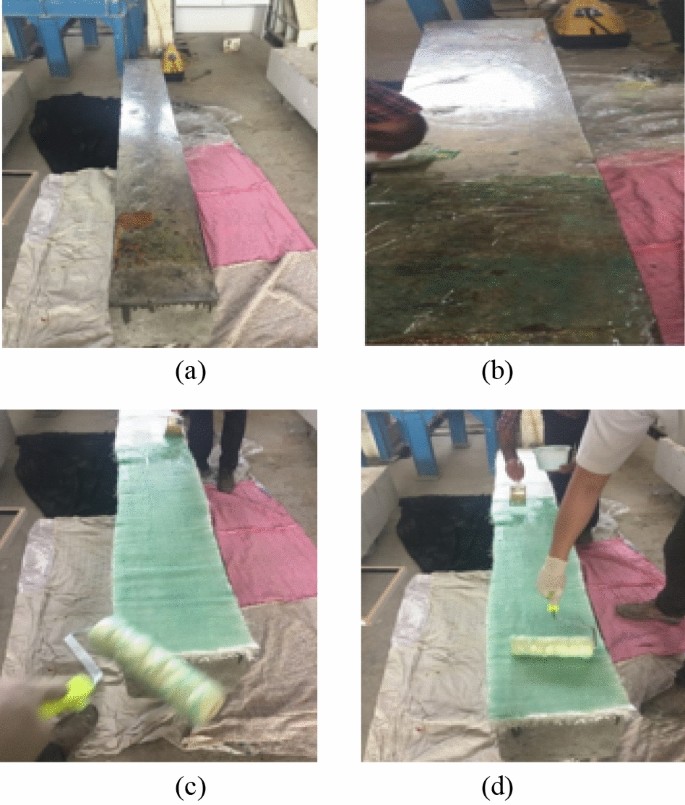
Resining of 3D-fiberglass: a cleaning the surface, b distributing 40% of the total quantity of resin, c placing 3D-fiberglass on a concrete surface, and d impregnating layers and surface.
-
Distributing 40% of the total quantity of resin onto the surface of the molds with a roll; see Fig. 5b.
-
Placing 3D-fiberglass on a concrete surface; see Fig. 5c.
-
Rolling resin gently and firmly until all of it has fully impregnated the layers and surface and the required thickness has been obtained; see Fig. 5d.

2.2 Material Property
In order to determine the compressive strength of concrete, five cubic concrete specimens with the dimensions of 150 × 150 × 150 (mm) were tested (BS8500-2, 2014). The 28-day compressive strength of the specimens was 33 MPa. The mechanical properties of the steel reinforcements, including the elastic modulus, yield stress, and ultimate strength were 191 GPa, 379 MPa, and 550 MPa, respectively. Three samples of each type of reinforcement were subjected to uniaxial tensile testing.
Carbon FRP, glass FRP, 3D-fiberglass, concrete repairs, and epoxy resin were used for strengthening the beams. The specification and mechanical properties of the materials used are shown in Tables 2, 3, 4, 5 and 6.
2.3 Experimental Setup and Instruments
All the beams were tested with a four-point bending machine at the structural laboratory of Semnan University, as illustrated in Figs. 6 and 7. The clear span of the specimens was 2000 mm, and the distance between loading points was 600 mm; see Fig. 7. Three multiple linear variable displacement Transducers (LVDT) were installed at the bending zone to measure the mid-span deflections independently. The locations of the LVDTs are shown in Fig. 7. The load was applied monotonically using a hydraulic jack with a total capacity of 1000 kN. Two bearing plates were placed under the loading points to prevent local failure of the specimens due to concrete crushing (see Fig. 7). It should be noted that the load was applied until the specimens failed.

Schematic diagram of test setup and instrumentation.

A real view of test setup and instrumentation.
3 Experimental Results and Discussion
The effect of 3D-fiberglass versus FRP, strengthening configuration and material properties on the performance of tested beam specimens are discussed in this part. The cracking load (Pcr), yielding load (Py), ultimate load (Pu), displacement corresponding to cracking load (Δcr), displacement corresponding to yielding load (Δy), displacement at ultimate load (Δu), flexural capacity improvement due to strengthening and observed failure mode of each specimen are presented in Table 7.
3.1 Mid-span Load–Displacement Curves
Load versus mid-span deflection curves of all the tested beam specimens are shown in Fig. 8. All the presented curves in Fig. 8 are characterized by three distinct stages up to maximum load: (1) stage I: un-cracked concrete; (2) stage II: development of cracking up to yielding of steel reinforcement; and (3) stage III: post-yielding response up to failure. Any difference between the curves of the strengthened beams and the reference one is due to the difference in the performance of the FRP and 3D-fiberglass and strengthening methodology. The performance of the strengthening materials was more visible during stages II and III, at which the steel reinforcement was yielding. At stage II, both steel reinforcement and strengthening materials contributed to actively absorbing the applied loads and helped to increase the flexural capacity. During stage III, the FRP and 3D-fiberglass became the main parameters that improved the flexural capacity. The behavior of all specimens after the peak load was approximately the same. All strengthened beams showed a dramatic drop in strength immediately after the failure of FRP or 3D-fiberglass. The load–displacement curves of the beams are compared in Fig. 9a. Fig. 9b displays the increase of flexural capacity of the strengthened beam specimens compared to the REF beam. It is shown that the R3DTR (the strengthened beam with 3D-fiberglass) and RGFRP (the strengthened beam with GFRP) specimens have the highest and lowest flexural capacity growth, with 19% and 8.4%, respectively.

Load–displacement curves of the tested beams: a REF specimen, b RCFRP specimen, c RGFRP specimen, and d R3DTR specimen.

Comparison of the specimens: a Load–displacement curves of the tested beams, and b increase of the flexural capacity of the strengthened beams in comparison with the REF beam.
3.2 Failure Mode and Crack Pattern
Concrete crushing and fiber rupture were two types of failure modes expected in the strengthened beams. These failure modes were presented by ACI 440.2R.17 (ACI, 2017) and classified as flexural failure assortment. All the beams failed in flexural mode and demonstrated severe flexural cracking, which is correlated with previous research (Choi et al., 2013; Choobbor et al., 2019; Raoof et al., 2017; Salama et al., 2019). Failure mechanisms and details of failure modes of each specimen are presented in Figs. 10, 11, 12, 13 and Table 7 and discussed in the following sections.

Failure mechanism and details of failure modes of REF beam specimen.

Failure mechanism and details of failure modes of RCFRP specimen.

Failure mechanism and details of failure mode of RGFRP specimen.

Failure mechanism and details of failure modes of R3DTR specimen.
3.2.1 REF Specimen
Fig. 10 shows the deflection and crack patterns of the REF beam at failure load. In this specimen, flexural failure occurred after large, severe, and symmetrical cracks appeared in the moment zone. This was due to the yielding of the tensile reinforcements and concrete crushing in the compressive zone, which was the expected failure type in the under-reinforced beams. These cracks first appeared at the mid-span and extended towards the supports. All flexural cracks spread from the soffit of the beam. Shear cracks did not appear at any point during the testing. The yield and ultimate load of the specimen were 134.17 kN and 162.5 kN, respectively. The corresponding mid-span deflections were 8.19 mm and 33.6 mm, respectively.
3.2.2 RCFRP Specimen
The RCFRP beam was strengthened using a CFRP sheet on the bottom and a 200-mm CFRP wrapping at the end anchorage of the beam. The observed failure mode in this beam was the rupture of the FRP sheet. As seen in Fig. 11a, b, the FRP rupture occurred at the moment zone. Moreover, the fractured surface is shown in Fig. 11b, c. When the longitudinal CFRP rupture occurred, there was no crushing in the compressive zone, which reveals that the strain in the FRP reached its design rupture before the concrete reached its ultimate strain which correlates with Alagusundaramoorthy et al., (2003). Furthermore, the RCFRP specimen experienced a symmetrical bending cracking pattern. Both bending and shear cracks were observed at the failure points. The yield and ultimate loads of the specimen were 157.8 kN and 179.8 kN, respectively. Their corresponding mid-span deflections were 8.09 mm and 16.01 mm, respectively.
3.2.3 RGFRP Specimen
The RGFRP specimen was strengthened with one sheet of GFRP at the bottom and a 200-mm GFRP wrapping at the end anchorage of the beam. The RGFRP beam exhibited a symmetrical cracking pattern, as seen in Fig. 12a. At first, minor FRP debonding occurred at the force corresponding to 160 kN (Fig. 12a, b) and as the force increased, the FRP debonding progressed until the rupture of the longitudinal GFRP sheet occurred outside the moment zone and near the end anchorage, as seen in Fig. 12c. It should be noted that although providing the end anchorage at the end of beam somehow prevented the FRP from debonding, slippage of fibers finally occurred in the region where the longitudinal GFRP sheet met the end anchorage. This is also reported by Papakonstantinou et al. (2001). It means that the substrate could not sustain the FRP force, and the concrete did not reach its maximum usable strain. The yield and ultimate load of the specimen were 150 kN and 176.167 kN, respectively, and their corresponding mid-span deflections were 8.43 mm and 20.86 mm, respectively.
3.2.4 R3DTR Specimen
In addition to 800 mm GFRP wrapping at both sides of the beam out of the bending zone, the R3DTR beam was strengthened using a longitudinal 3D-fiberglass sheet. This specimen showed a symmetrical and widespread cracking pattern. As seen in Fig. 13a, concrete crushing occurred in the compressive zone when the applied load was equal to 190 kN. At the loading point of 194.833 kN, the GFRP wrapped at the end anchorage ruptured, as seen in Fig. 13b, and consequently, the 3D-fiberglass ruptured from exactly the same region, as seen in Fig. 13c. Although the R3DTR specimen could not delay the yielding of rebars, compared to the FRP-reinforced specimens, it had a significant effect on the improvement of maximum capacity. The R3DTR beams showed better performance among all the beams in terms of crack pattern and flexural capacity, attesting to the efficiency of 3D-fiberglass.
3.3 Additional Tests Based on Experimental Results
Analysis of the results obtained from the tests indicated that the beam strengthened with 3D-fiberglass exhibited a better performance (R3DTR) than beams strengthened with FRP (RCFRP and RGFRP) in terms of flexural capacity and crack pattern. However, it should be taken into account that resin and 3D-fiberglass are extremely expensive materials. Therefore, to find a promising alternative to resin, to achieve optimum 3D-fiberglass length, and to investigate the effects of the different 3D-fiberglass configurations, two other specimens, i.e., R3DTG and R3DTRB, were constructed to be tested. Details of these two new specimens are shown in Fig. 14 and Table 8.

Details of the additional tested beams: a details of R3DTG specimen, with concrete repairer injected into the 3D-fiberglass, and b details of R3DTRB specimen, typical wrapping of 3D-fiberglass at bottom and extended on sides with GFRP wrapping (dimensions in mm).
In order to reduce the consumption of resin, two types of materials, i.e., grout and concrete repairer, were considered as possible replacements. The concrete repairer was ultimately selected because it had finer aggregates than grout. Thus, in one of the specimens (R3DTG), a polyurethane gun was used to inject concrete repairer into the 3D-fiberglass; see Table 8. Then the injected 3D-fiberglass was cured for 7 days. Finally, the composite was attached to the concrete surface by means of epoxy resin, as shown in Fig. 14a.
The second additional beam (R3DTRB) was designed to investigate different 3D-fiberglass configurations. In this specimen, the length of the 3D-fiberglass sheet was reduced from 2500 to 1800 mm. In addition, the 3D-fiberglass extended 100 mm on each side of the beam to provide better lateral confinement, as can be seen in Fig. 14b.
3.3.1 Efficiency of Concrete Repairer Versus Resin
The mid-span load–displacement curve of R3DTR (with resin) and R3DTG (with concrete repairer) specimens are compared in Fig. 15. The crack, yield and ultimate loads of the R3DTG specimen were 45 kN, 145.6 kN and 170.5 kN, respectively, with corresponding mid-span deflection of 1.16 mm, 8.01 mm and 31.05 mm, respectively. The results indicate that the R3DTR specimen in terms of flexural capacity and ductility, performed better than the R3DTG specimen. In the R3DTG specimen, failure occurred after large and widespread cracks appeared in the moment zone (Fig. 16). This was due to the yielding of the tensile reinforcements and consequent concrete crushing at the compressive zone. After loading, it was observed that composite (3D-fiberglass and concrete repairer) remained intact. In the R3DTR specimen, a strong connection between 3D-fiberglass and concrete was established, while in the R3DTG specimen, this strong connection was not established. Fig. 15 shows that, although the behavior of R3DTG in un-cracked and cracking zones up to the yielding point was similar to the other specimens, in the post-yielding zone, its behavior was more similar to the REF specimen. This means that, before yielding, epoxy resin made a good connection between concrete and composite (3D-fiberglass and concrete repairer), but after yielding point, the effects of epoxy resin disappeared. The observed failure mode was unexpected for this strengthened specimen.

Load–displacement curves of tested beams: a R3DTG specimen, and b REF, R3DTR and R3DTG specimens.

Failure mechanism and details of failure mode of R3DTRB specimen.
3.3.2 Efficiency of 3D-Fiberglass Extension
The mid-span load–displacement curves of the R3DTR and R3DTRB specimens are shown in Fig. 17. The crack, yield and ultimate load of the R3DTRB specimen were 52 kN, 154.2 kN and 216.2 kN, respectively, and the corresponding mid-span deflection was 1.41 mm, 7.39 mm, and 20.55 mm, respectively. The comparison between the curves revealed that the contribution of the extension of 3D-fiberglass in R3DTRB specimen in improving the flexural capacity was approximately 22 kN (nearly 11% higher than the capacity of R3DTR specimen). Furthermore, the R3DTRB, in comparison with R3DTR had 16% less deflection at ultimate load. In addition, the R3DTRB showed about 11% more flexural strength than the R3DTR, demonstrating the effectiveness of 100 mm extension of 3D-fiberglass on the beam sides. During the plastic deformation phase, the R3DTR displayed more ductility than the R3DTRB (about 8%) and both R3DTR and R3DTRB showed lower ductility than REF specimen. In terms of failure mode, both specimens failed due to 3D-fiberglass rupture. In the R3DTRB specimen, the 3D-fiberglass rupture occurred at the moment zone. In this specimen, when 3D-fiberglass ruptured, there was no sign of concrete crushing in the compressive zone (Fig. 18a, b). Moreover, the fracture surface of the R3DTRB specimen is shown in Fig. 18b, c. Therefore, it is concluded that using this strengthening scheme can significantly improve the flexural capacity, delay the yielding of rebars and change the failure mode zone.

Load–displacement curves of tested beams: a R3DTRB specimen, and b comparison of REF, R3DTR and R3DTRB specimens.

Failure mechanism and details of failure mode of R3DTRB specimen.
3.4 Ductility
Steel absorbs a large amount of inelastic energy in its yielding and hardening process. In contrast, due to its lack of plasticity and its brittle behavior, FRP does not provide significant energy absorption. Therefore, RC beams strengthened with FRP sheets are not expected to experience failure with adequate ductility and warning signs. The ductility of RC beams depends on the load–displacement curve of the beam. This measurement will provide an indication of the amount of plastic deformation that a beam can endure prior to failure. Ductility index (\({\mu }_{d})\) can be estimated as follows:
where \({\Delta }_{u}\) and \({\Delta }_{y}\) are deflections at the ultimate and yielding loads, respectively. Table 9 and Fig. 19 summarize the ductility indices of each of the six investigated beams: i.e., the control beam and the beams strengthened with 3D-fiberglass and FRP. In the third column of the table, the ductility ratios of the strengthened specimens to the control specimen (REF) are presented. Due to high modulus of elasticity of carbon, the beams strengthened with CFRP show lower ductility among the tested beams. The ductility of strengthened specimens was less than that of the REF specimen by 10–53%. The present behavior is identical with the observed results by previous research studies (Galal & Mofidi, 2009; Hawileh, et al., 2014; Kim & Shin, 2011). In addition, the ductility of the beams strengthened with 3D-fiberglass (R3DTR, R3DTG, and R3DTRB) is higher than that of the beams strengthened with FRP (RCFRP and RGFRP); this highlights the efficiency of using 3D-fiberglass in ductility of the specimens. It can be concluded that strengthening the beam with 3D-fiberglass provides better strengthening performance by achieving higher ductility.

Ductility indices and energy ratio of all specimens.
In the beams strengthened with 3D-fiberglass, the R3DTR, R3DTG, and R3DTRB specimens showed better ductility in comparison with the RGFRP specimen—with 58%, 56%, and 12% higher ductility for the R3DTR, R3DTG, and R3DTRB specimens, respectively.
The main parameter that affects the ductility of the strengthened specimens is the brittle behavior of FRP and 3D-fiberglass sheets. It seems that the R3DTRB, due to its 3D-fiberglass configuration (U-wrap), experienced brittle failure, with the ductility of this specimen decreasing in comparison with the other specimens strengthened with 3D-fiberglass.
4 Numerical Simulation of Beams Strengthened with FRP Sheet
In the last few years, a number of studies have been carried out to numerically investigate the performance of the RC elements strengthened with FRP (Abaqus et al., 2002; Abouali et al., 2019; Barzant, 1986; Chellapandian et al., 2018; Coronado & Lopez, 2006; Lee & Fenves, 1998; Lubliner et al., 1989; Ouni & Raza, 2021; Raza & Rafique, 2021; Raza, El Ouni, et al., 2021; Raza, Manalo, et al., 2021). They have used different methods in the simulation of concrete, FRP sheets, and the bond between the concrete and FRP. The aim of this section is to investigate the advantages and accuracy of a finite element simulation in predicting the behavior of the FRP-strengthened beams. To this aim, the control beam with no strengthening (REF specimen), and two beams strengthened with CFRP and GFRP sheets (i.e., RCFRP and RGFRP specimens) were selected to be simulated. To provide a comprehensive realization of flexural response of RC beams, the numerical models were developed in Abaqus software version 6.14. The outcome from the numerical simulation was compared with the corresponding experimental results.
4.1 Material Constitutive Behavior
4.1.1 Concrete Model
There are different methods such as the concrete damage plasticity (CDP), Drucker–Prager, smeared cracking, and brittle crack, in Abaqus to define the nonlinear behavior of concrete. Among them, the CDP model can show the best performance to simulate the complex behavior of concrete strengthened with FRP (Coronado & Lopez, 2006; Ouni & Raza, 2021; Raza & Rafique, 2021; Raza, El Ouni, et al., 2021). Therefore, in this study, the CDP model was used to simulate the nonlinear behavior of concrete. This approach supposed that compressive crushing and tensile cracking are the key failure mechanism of concrete. These phenomena are the consequences of micro-cracking (Barzant, 1986). Lubliner et al. (1989) and Lee and Fenves (1998) proposed the thorough details of these ideas' mathematical implementation. Moreover, the CDP model provides the ability to calibrate the behavior of concrete through its diverse parameters precisely. The concrete mechanical properties are presented in Table 10. The tensile behavior and compressive stress–strain curve of concrete are presented in Figs. 20 and 21, respectively.

Tensile behavior of concrete (Lubliner et al., 1989).

Compressive stress–strain curve of concrete (Lubliner et al., 1989).
The values of the plasticity parameters in the CDP model are estimated based on the suggested values in Abaqus and then calibrated using sensitivity analysis to ensure the best agreement with the experimental result for three simulated beams. In this study, the angle of dilation is varied from 20 to 40 (Coronado & Lopez, 2006) and viscosity parameter is varied from 0.001 to 0 (Ouni & Raza, 2021; Raza & Rafique, 2021; Raza, Manalo, et al., 2021). Sensitivity analysis of viscosity and dilation angle results are presented in Fig. 22. The plasticity parameters are presented in Table 11.

Sensitivity analysis of CDP parameters.
4.1.2 Steel Model
An isotropic hardening plasticity behavior model was adopted for the transverse and longitudinal steel reinforcements that are described in Abaqus et al. (2002). The modulus of elasticity of steel, obtained experimentally, was equal to 191 GPa. The interaction between reinforcing bars and concrete was imitated by embedded region constraint (Raza & Rafique, 2021).
4.1.3 FRP Model
FRP displayed elastic behavior up to brittle failure at the ultimate tensile stress. The FRP sheets were simulated using ''LAMINA'' material type in Abaqus et al. (2002) and Ouni and Raza (2021)). The defined properties of FRP sheets were similar to the properties mentioned in Table 2. The characteristics of the elastic performance of FRP sheets are reported in Table 12 (Ouni & Raza, 2021).
4.2 Element Types and Boundary Condition
To model FRP sheets and concrete beams, four-node shell elements with reduced integration (S4R) and eight-node brick elements (C38DR) were considered. The reinforcement was presented by two-node linear truss elements (T3D2) that simulate only axial stiffness. Perfect bonding between the FRP and the concrete was assumed, which was achieved by tying the FRP to adjacent the concrete by means of the tie option in Abaqus. A mesh size of 40 and 55 mm was used for concrete and steel, respectively. A mesh-sensitivity study was carried out to select an appropriate mesh size. Using 40 mm mesh size for rebars causes a more extended calculation with no remarkable effect on the results. The best calibration of the FE models done with experimental results obtained when the boundary condition of supports of the simulated specimens were defined as allowed for rotation and fixed for translation (Ouni & Raza, 2021; Raza, Manalo, et al., 2021). These boundary conditions are fully matched with the experimental setup. The boundary condition and mesh configuration are shown in Fig. 23. Mesh sensitivity analysis results are presented in Fig. 24. In addition, loading was exerted under a displacement-controlled method by applying monotonically vertical displacement to all nodes at the loading surface until the failure of the beam (Table 12).

Mesh configuration and boundary condition.

Mesh sensitivity analysis results for the reference specimen with three mesh sizes of 40, 50 and 60 mm.
4.3 Analyses Results and Verification
This section presents the numerical analyses results of the simulated beams, i.e., the control beam with no strengthening (the REF specimen) and two strengthened beams with CFRP and GFRP sheets (i.e., the RCFRP and RGFRP specimens). Comparison of the load–displacement curves of the FE model and experimental specimens is shown in Fig. 25. The results indicated that the proposed numerical models were compatible with experimental tests results.

Comparison between load–displacement curves of the simulated FE models and the tested specimens: a REF specimen, b RCFRP specimen, and c RGFRP specimen.
4.4 Numerical Failure Mode of Strengthened Beams
Failure modes of numerical modeled RGFRP and RCFRP specimens are compared with the experimental ones in Fig. 26. Observed failure modes have good agreement with the experimental results. By increasing the applied load, concrete crushing was gradually beginning to expand from the mid-span of beams to the other regions. In the RCFRP specimen, most of the stresses are concentrated in the middle of the FRP sheet, while in the RGFRP specimen, it was at the supports.

Numerical and experimental failure modes of strengthened beams: a RCFRP, and b RGFRP.
5 Conclusion
This study aims to investigate the structural performance of reinforced concrete (RC) beams strengthened with 3D-fiberglass and fiber-reinforced polymer (FRP) sheets. For this purpose, six RC beams were fabricated, strengthened, and tested under four-point bending machine. Failure mode, crack development, flexural capacity, ductility, the effectiveness of wrapping, and the performance of epoxy resin in comparison with concrete repairer were studied between various beams. The main findings of this study can be summarized as follows:
-
The effectiveness of 3D-fiberglass with resin was greater than that of FRP systems in terms of flexural capacity. The R3DTR and RGFRP specimens, compared to the control specimen, had the highest and lowest flexural capacity growth, with 19% and 8.4%, respectively. Moreover, the U-wrap of 3D-fiberglass had notable increase in the ultimate load (up to 30% compare with the REF specimen), showing the effectiveness of the strengthening scheme.
-
Strengthening of the specimens by adding sheets to the surface of the concrete resulted in reduced ductility. The amount of ductility reduction in the specimens with 3D-fiberglass was less than in the specimens strengthened with FRP. In addition, U-wrap of 3D-fiberglass reduced (up to 27%) the ductility compared with specimens strengthened with 3D-fiberglass without any wrapping.
-
The comparison between the resin and concrete repairer performance, when combined with 3D-fiberglass, showed that the combination of resin and 3D-fiberglass performed more effectively in flexural capacity, and ductility.
-
The failure modes of 3D-fiberglass and resin systems, FRP systems, and the reference beam investigated in this study were rupture of 3D-fiberglass, rupture of FRP, and concrete crushing, respectively.
-
Results of the proposed numerical model of the beams strengthened with FRP were compatible with the results of the experiment. This model could be used for further study on predicting the capacity of FRP-strengthened beams.
6 Recommendations for Future Work
-
Based on the observed results and by considering the environmental point of view, it is important to optimize the usage of 3D-fiberglass material. To this aim, the authors recommend studying the optimum fiber length in a partially strengthened beam.
-
The shear performance of these beams strengthened with 3D-fiberglass could be investigated. In the present study, the bending behavior of 3D-fiberglass was investigated; however, the shear behavior of the strengthened beams needs more investigation.
-
Considering FE simulation as an accessible and cost-effective tool, more studies are needed to find an efficient and accurate 3D-fiberglass simulation.
Availability of data and materials
Some or all data, models, or code that support the findings of this study are available from the corresponding author upon reasonable request.
References
Abaqus/Explicit User's Manual, Version 6.3. Hibbitt, Karlson and Sorenson, Inc. Pawtucket, RI. 2002.
Abouali, S., Sahverdi, M., Ghasemie, M., & Motavalli, M. (2019). Nonlinear simulation of reinforced concrete beams retrofitted by near-surface method iron-based shape memory alloys. Eng Struc, 187, 133–148.
ACI 440.2R-17. Guide for the design and construction of externally bonded FRP systems for strengthening of concrete structures. Michigan: American concrete institute, ACI Committee 440; 2017.
Alagusundaramoorthy, P., Harik, I. E., & Choo, C. C. (2003). Flexural behavior of RC beams strengthened with carbon reinforced polymer sheets or fabric. Journal of Compos for Struct, 7, 292–301.
Ali, O., Biguad, D., & Riahi, H. (2018). Seismic performance of reinforced concrete structures strengthened with FRP laminates using a reliability-based advanced approach. Composite Part B, 139, 238–248.
Al-Jelawy, H. (2013). Experimental and numerical investigations on bond durability of CFRP strengthened concrete members subjected to environmental exposure. MSc Thesis. University of Central Florida. https://stars.library.ucf.edu/etd/2730
Al-Jelawy, H. M., & Mackie, K. R. (2020). Flexural behavior of concrete beams strengthened with polyurethane-matrix carbon-fiber composites. Journal of Composites for Construction, 24(4), 04020027.
Al-Jelawy, H. M., & Mackie, K. R. (2021). Durability and failure modes of concrete beams strengthened with polyurethane or epoxy CFRP. Journal of Composites for Construction, 25(3), 04021021.
Asaee, Z., Shadlou, S., & Taheri, F. (2015). Low-velocity impact of fiberglass/magnesium FMLs with a new 3D fiberglass fabric. Composite Structures, 122, 155–165.
Attari, N., Amziane, S., & Chemrouk, M. (2012). Flexural strengthening of concrete beams using CFRP, GFRP and hybrid FRP sheets. Construction and Building Materials, 37, 746–757.
Barzant, Z. (1986). Mechanics of distributed cracking. Applied Mechanics Reviews, 39, 675–705.
BS 8500-2. (2014). Concrete—Complimentary British standard to BS EN 206—Part 2: Specification for constituent materials and concrete. British Standards Institution, London, 2014
Camata, G., Spacone, E., & Zarnic, R. (2007). Experimental and nonlinear fiite element studies of RC beams strengthened with FRP plates. Composite Part B, 38, 277–288.
Ceroni, F., Marisa, P., Bilotta, A., & Nigro, E. (2012). Bond behavior of FRP NSM system in concrete element. Composite Part B, 43, 99–109.
Chan, T., & Mackie, K. R. (2020). Flexural strengthening of reinforced concrete beams using externally bonded polyurethane carbon fiber-reinforced polymer composite systems. ACI Structural Journal 117(6).
Chellapandian, M., Praksh, S. S., & Sharma, A. (2018). Experimental and finite element studies on the flexural behavior of reinforced concrete element strengthened with hybrid FRP technique. Composite Structures, 208, 466–478.
Chen, C., Yang, Y., Jinbo, Y., Yu, J., Tan, H., Sui, L., & Zhou, Y. (2020a). Eco-friendly and mechanically reliable alternative to synthetic FRP in externally bonded strengthening of RC beams: Natural FRP. Composite Structures, 241, 112081.
Chen, C., Yang, Y., Zhou, Y., Xue, C., Chen, X., Wu, H., Sui, L., & Li, X. (2020b). Comparative analysis of natural fiber reinforced polymer and carbon fiber reinforced polymer in strengthening of reinforced concrete beams. Jourl of Clnr Prod., 263, 121572.
Chen, W., Pham, T. M., Sichembe, H., Chen, L., & Hao, H. (2018). Experimental study of flexural behavior of RC beams strengthened by longitudinal and U-shaped basalt FRP sheet. Composite Part B, 134, 114–126.
Choi, E., Utai, N., & Kim, H. S. (2013). Experimental and analytical investigations on debonding of hybrid FRPs for flexural strengthening of RC beams. Composite Part B, 45, 248–256.
Choobbor, S. S., Hawileh, R. A., Abu-Qbeidah, A., & Abdalla, J. A. (2019). Performance of hybrid carbon and basalt FRP sheets in strengthening concrete beams in flexure. Composite Structures, 227, 111337.
Coronado, C. A., & Lopez, M. L. (2006). Sensitivity analysis of reinforced concrete beams strengthened with FRP laminate. Cement and Concrete Composites, 28, 102–114.
Correia, L., Sena-Cruz, J., Michels, J., França, P., Pereira, E., & Escusa, G. (2017). Durability of RC slabs strengthened with prestressed CFRP laminate strips under different environmental and loading conditions. Composite Part B, 125, 71–88.
Dong, J., Wang, Q., & Guan, Z. (2013). Structural behavior of RC beams with external flexural and flexural-shear strengthening by FRP sheets. Composite Part B, 44, 604–612.
Elsanadedy, H. M., Abbas, H., Almusallam, T. H., & Al-Salloum, Y. A. (2019). Organic versus inorganic matrix composite for bond-critical strengthening applications of RC structure—state-of-the-art review. Composite Part B, 174, 106947.
Fan, H., Chao, L., Chen, H., Kuang, N., Yang, C., Huang, S., & Jiang, Y. (2012). Ductile deformation mechanism and designing instruction for integrated woven textile sandwich composites. Composites Science and Technology, 72, 1338–1343.
Fan, H., Zhou, Q., Yang, W., & Jingjing, Z. (2010). An experimental study on the failure mechanism of woven textile sandwich panels under quasi-static loading. Composite Part B, 41, 686–692.
Firmo, J. P., Arruda, M. R. T., & Correia, J. R. (2015). Numerical simulation of the fire behavior of thermally insulted reinforced concrete beams strengthened with EBR-CFRP strips. Composite Structures, 126, 360–370.
Galal, K., & Mofidi, A. (2009). Strengthening of RC beams in flexure using new hybrid FRP sheet ductile anchor system. Journal of Composite for Structures, 13(3), 217–225.
Haji, M., Naderpour, H., & Kheyroddin, A. (2019). Experimental study on influence of proposed FRP strengthening techniques on RC circular short columns considering different type of damage index. Composite Structures, 209, 112–128.
Hawileh, R. A., RasheEd, H. A., Abdalla, J. A., & Tamimi, A. K. (2014). The behavior of RC beams strengthened with EB hybrid fiber reinforced polymer system. Material and Design, 53, 972–982.
Jahami, A., Temsah, Y., Khatib J., & Sonebi M. (2018). Numerical study for the effect of carbon fiber reinforced polymers (CFRP) sheets on structural behavior of posttensioned slab subjected to impact loading, Proceedings of the Symposium on Concrete Modelling—CONMOD2018, RILEM PRO 127, Edited by Erik Schlangen et al., pp. 259–267.
Jahami, A., Temsah, Y., & Khatib, J. (2019). The efficiency of using CFRP as a strengthening technique for reinforced concrete beams subjected to blast loading. International Journal of Advanced Structural Engineering, 11(4), 411–420.
Jahami, A., Temsah, Y., Khatib, J., Baalbaki, O., & Kenai, S. (2021). The behavior of CFRP strengthened RC beams subjected to blast loading. Magazine of Civil Engineering., 103(3), 10309.
Kara, I. F., & Ashour, A. F. (2012). Flexural performance of FRP reinforced concrete beams. Composite Structures, 94, 1616–1625.
Kashi, A., Ramezanianpour, A. A., Moodi, F., & Malekitabar, H. (2019). Effect of aggressive marine environment on strain efficiency factor of FRP-confined concrete. Construction and Building Materials, 222, 882–891.
Kim, H. S., & Shin, V. (2011). Flexural behavior of reinforced concrete beams retrofitted with hybrid fiber reinforced polymer under sustained loads. Composite Structures, 93, 802–811.
Ku, H., Wang, H., Pattarachiayakoob, N., & Trada, M. (2011). A review on tensile properties of natural fiber reinforced polymer composite. Composite Part B, 42, 856–873.
Lee, J., & Fenves, L. G. (1998). Plastic-damage concrete model for earthquake analysis of dams. Earthquake Engineering and Structural Dynamics, 27(9), 937–956.
Li, M., Wang, S., Zhang, Z., & Wu, B. (2009). Effect of structure on the mechanical behavior of three-dimensional spacer fabric composite. Applied Composite Materials, 16, 1–14.
Lubliner, J., Oliver, J., & Onate, S. E. (1989). Plastic-damage model for concrete. International Journal of Solids and Structures, 25(3), 299–326.
Matthys, S., & Taerwe, L. (2006). Evaluation of ductility requirements in current design guidelines for FRP strengthening. Cemtent and Concrete Composites, 28, 845–856.
Moradi, E., Naderpour, H., & Kheyroddin, A. (2020). An experimental approach for shear strengthening of RC beams using a proposed technique by embedded through-section FRP sheets. Composite Structure, 238, 111988.
Mosallam, A. S., & Nasr, A. (2017). Structural performance of RC shear walls with post-construction openings strengthened with FRP. Composite Part B, 115, 488–504.
El Ouni, M.O., & Raza, A. (2021). Data-driven analysis of concrete-filled steel-tube CFRP-confined NSC columns. Mechanics of advanced materials and structures
Papakonstantinou, C. G., Petrou, M. F., & Harries, K. A. (2001). Fatigue behavior of RC beams strengthened with GFRP sheets. Journal of Composites for Structures, 5, 246–253.
Raoof, S. M., Koutas, L. N., & Bournas, D. A. (2017). Textile-reinforced mortar (TRM) versus fiber-reinforced polymers (FRP) in flexural strengthening of RC beams. Construction and Building Materials, 151, 279–291.
Rasheed, H. A., Abdalla, J., Hawileh, R., & Al-Tamimi, A. K. (2017). Flexural behavior of reinforced concrete beams strengthened with externally bonded aluminum alloy plates. Engineering Structures, 147, 473–485.
Raza, A., El Ouni, M. O., Zaman Khan, Q. U., & Berradia, M. (2021). Structural assessment of eccentrically loaded GFRP reinforced circular columns: experiments and finite element analysis. Composite Structures, 275, 114528.
Raza, A., Manalo, C. A., Rafique, U., AlAjarmeh, S. O., & Zaman Khan, Q. U. (2021). Concentrically loaded recycled aggregated geopolymer concrete columns reinforced with GFRP bars. Composite Structures, 268, 113968.
Raza, A., & Rafique, U. (2021). Efficiency of GFRP bars and hoops in recycled aggregated concrete columns: experimental and numerical study. Composite Structures, 255, 112986.
Renyuan, Q., Zhou, A., & Lau, D. (2017). Effect of reinforcement ratio on the flexural performance of hybrid FRP reinforced concrete beams. Composite Part B, 108, 200–209.
Sadighi, M., & Hoseini, S. A. (2013). Finite elements simulation and experimental study on mechanical behavior of 3D woven glass fiber composite sandwich panels. Composite Part B, 55, 158–166.
Salama, A. S. D., Hawileh, R. A., & Abdall, J. A. (2019). Performance of externally strengthened RC beams with side-bonded CFRP sheets. Composite Structures, 212, 281–290.
Siddika, A., Al-Mamun, M. A., Alyousef, R., & Amran, Y. H. M. (2019). Strengthening of reinforced concrete beams by using fiber-reinforced polymer composite: A review. Journal of Building Engineering, 25, 100798.
Skuturna, T., & Valivonis, J. (2016). Experimental study on the effect of anchorage systems on RC beams strengthened using FRP. Composite Part B, 91, 283–290.
Triantafyllou, G. G., Rousakis, T. C., & Karabins, A. I. (2017). Corroded RC beams patch repaired and strengthened in flexure with fiber-reinforced polymer laminate. Composite Part B, 112, 125–136.
Van Vuure, A. W., Ivens, J. A., & Verpoest, I. (2000). Mechanical properties of composite panels based on woven sandwich-fabric performs. Composite Part A, 31, 671–680.
Van Vuure, A. W., Pflug, J., Ivens, J. A., & Verpoest, I. (2000). Modeling the core properties of composite panels based on woven sandwich-fabric performs. Composites Science and Technology, 60, 1263–1276.
Yazdani, N., & Goucher, E. (2015). Increasing durability of lightweight concrete through FRP wrap. Composite Part B, 82, 166–172.
Zhang, Y., Li, X., Zhu, Y., & Shao, X. (2020). Experimental study on flexural behavior of damaged reinforced concrete (RC) beams strengthened by toughness-improved ultra-high performance concrete (UHPC) layer. Composite Part B, 186, 107834.
Zhou, A., Qin, R., Feo, L., Penna, R., & Lau, D. (2017). Investigation on interfacial detect criticality of FRP-bonded concrete beams. Composite Part B, 113, 80–90.
Acknowledgements
The authors would like to thank the department of civil engineering at Semnan University for its support. The help of Mr. Mohammad Vahidpour from Shahrood University, Mohammad Beiranvand from Semnan University, and lab manager Mr. Mohammad Bakhshaii is gratefully acknowledged.
Funding
There has been no officially assigned funding regarding this manuscript.
Author information
Authors and Affiliations
Contributions
MV: experimentation, validation, software, formal analysis, investigation, writing original/final draft and writing—review/editing. AK: conceptualization, supervision, project administration, review/editing and formal analysis. MK: supervision, project administration, conceptualization, validation, software, formal analysis, writing original/final draft and writing—review/editing. All authors read ad approved the final manuscript.
Authors’ information
Mahdi Vahidpour is graduate master student at Department of Civil Engineering at Semnan University. His research interests include structural analysis using finite element method (FEM), experimental methods in structural engineering and rehabilitation of structures.
Ali Kheyroddin is an Invited Visiting Scholar at the University of Texas at Arlington, Arlington, TX, and Distinguished Professor of Civil Engineering at Semnan University. He received his MS from Iran University of Science and Technology, Tehran, Iran, and his PhD from McGill University, Montreal, QC, Canada. He was the Chancellor of Semnan University for 8 years. His research interests include analysis and design of reinforced concrete structures, concrete properties, tall buildings, rehabilitation of existing buildings, and design of earthquake-resistant buildings.
Mahdi Kioumarsi is an Associate Professor at the Department of Civil Engineering and Energy Technology, Oslo Metropolitan University (OsloMet), Oslo, Norway. He has more than fifteen years’ experience with research on concrete, deteriorated concrete structures, fiber-reinforced concrete, and FE simulation, and has published in leading international conferences and journals. He did his Ph.D. in structural engineering at Norwegian University of Science and Technology (NTNU) in Trondheim, Norway.
Corresponding author
Ethics declarations
Competing interests
The authors declare no competing financial interest regarding this publication.
Additional information
Publisher's Note
Springer Nature remains neutral with regard to jurisdictional claims in published maps and institutional affiliations.
Journal information: ISSN 1976-0485 / eISSN 2234-1315
Rights and permissions
Open Access This article is licensed under a Creative Commons Attribution 4.0 International License, which permits use, sharing, adaptation, distribution and reproduction in any medium or format, as long as you give appropriate credit to the original author(s) and the source, provide a link to the Creative Commons licence, and indicate if changes were made. The images or other third party material in this article are included in the article's Creative Commons licence, unless indicated otherwise in a credit line to the material. If material is not included in the article's Creative Commons licence and your intended use is not permitted by statutory regulation or exceeds the permitted use, you will need to obtain permission directly from the copyright holder. To view a copy of this licence, visit http://creativecommons.org/licenses/by/4.0/.
About this article

Cite this article
Vahidpour, M., Kheyroddin, A. & Kioumarsi, M. Experimental Investigation on Flexural Capacity of Reinforced Concrete Beams Strengthened with 3D-Fiberglass, CFRP and GFRP. Int J Concr Struct Mater 16, 18 (2022). https://doi.org/10.1186/s40069-022-00508-w
Received:
Accepted:
Published:
DOI: https://doi.org/10.1186/s40069-022-00508-w