- Open access
- Published:
Applying the Ferrocement Concept in Construction of Concrete Beams Incorporating Reinforced Mortar Permanent Forms
International Journal of Concrete Structures and Materials volume 8, pages 83–97 (2014)
Abstract
This paper presents the results of an investigation aimed at developing reinforced concrete beams consisting of precast permanent U-shaped reinforced mortar forms filled with different types of core materials to be used as a viable alternative to the conventional reinforced concrete beam. To accomplish this objective, an experimental program was conducted and theoretical model was adopted. The experimental program comprised casting and testing of thirty beams of total dimensions 300 × 150 × 2,000 mm consisting of permanent precast U-shaped reinforced mortar forms of thickness 25 mm filled with the core material. Three additional typical reinforced concrete beams of the same total dimensions were also cast to serve as control specimens. Two types of single-layer and double-layers steel meshes were used to reinforce the permanent U-shaped forms; namely welded wire mesh and X8 expanded steel mesh. Three types of core materials were investigated: conventional concrete, autoclaved aerated lightweight concrete brick, and recycled concrete. Two types of shear connections between the precast permanent reinforced mortar form and the core material were investigated namely; adhesive bonding layer between the two surfaces, and mechanical shear connectors. The test specimens were tested as simple beams under three-point loadings on a span of 1,800 mm. The behavior of the beams incorporating the permanent forms was compared to that of the control beams. The experimental results showed that better crack resistance, high serviceability and ultimate loads, and good energy absorption could be achieved by using the proposed beams which verifies the validity of using the proposed system. The theoretical results compared well with the experimental ones.
1 Introduction
Ferrocement is a construction material that proved to have superior qualities of crack control, impact resistance, and toughness, largely due to the close spacing and uniform dispersion of reinforcement within the material. One of the main advantages of ferrocement is that it can be constructed with a wide spectrum of qualities, properties, and cost, according to customer’s demand and budget. The ACI committee 549 published a general definition of ferrocement states that “Ferrocement is a type of thin wall reinforced concrete commonly constructed of hydraulic cement mortar reinforced with closely spaced layers of continuous and relatively small size wire mesh, the mesh may be made of metallic or other suitable materials” (ACI 2006).
Recently, ferrocement has received attention as a potential building material, especially for roofing of housing construction (National Academy of Sciences 1973) and has been used for several applications (Naaman 2000). Ferrocement has received attention as a potential building material. Many investigators have reported the physical and mechanical properties of this material, and numerous test data are available to define its performance (Naaman 1979; Yogendran et al. 1987; Korany 1996).
The ferrocement has been used as sole construction material and as a repair material. Al-Rifaei and Hassan (1994) presented the results of an experimental and theoretical study of the behavior of channel shaped ferrocement one-way bending elements. The results showed that this type of elements can undergo large deflections before failure and is suitable for construction of horizontally spanning unit for one-way bending. Fahmy et al. (2006, 2012) have used ferrocement laminate for constructing sandwich and hollow core precast panels for wall construction. Chandrasekhar Rao et al. (2008) reported the results of an experimental study on the strength and behavioral aspects of voided ferrocement channels for precast beams. Their test results indicated drop in flexural strength of the voided channels as compared with the solid ones. However, this drop is very negligible compared to the decrease in the weight of the member. Mays and Barnes (1995) presented the results of an experimental investigation to examine the feasibility of using ferrocement as a low permeability cover layer to reinforced concrete members located in environments, where there is a high risk of reinforcement corrosion. They found that the resistance to chloride penetration in accelerated ageing tests was enhanced by using styrene butadiene rubber or acrylic bond coat between the ferrocement forms and the concrete. They also reported that this protective cover could be precast and work as permanent formwork for the concrete element. They found the use of such permanent ferrocement formwork gave an increase in strength of 15 % over the conventional reinforced concrete. Singh et al. (1994) and Gregson and Dickson (1994) reported on the use of innovative combination of ferrocement and reinforced concrete to construct the distinctive exposed structure of the first floor slab of the Schlumberger Cambridge Research building. Fahmy et al. (1997a, 1997b, 1999) reported in the literature the results of investigations aimed at using ferrocement for repairing reinforced concrete beams, slabs, and columns. Their reported experimental results showed the effectiveness of using the ferrocement laminates for repairing these structural elements.
Recently Abdel Tawab et al. (2012) has presented the results of an experimental investigation to examine the feasibility and effectiveness of using precast U-shaped ferrocement laminates as permanent forms for construction of reinforced concrete beams. The precast permanent ferrocement forms were proposed as a viable alternative to the commonly used wooden and/or steel temporary forms. The authors used woven wire mesh, X8 expanded wire mesh, and EX156 expanded wire mesh for reinforcing the precast ferrocement forms. The precast ferrocement forms were filled with conventional concrete reinforced with two steel bars. Neither bonding agent not mechanical shear connection was used in that research to provide shear connection between the forms and the core. The reported results showed that high serviceability and ultimate loads, crack resistance control, and good energy absorption properties could be achieved by using the proposed ferrocement forms.
This paper presents a continuation of the investigation reported by Tawab et al. (2012). In the present investigation single and double layers of welded wire and X8 expanded steel meshes are used to reinforce the U-shaped forms. In addition, three types of core material are used to fill the reinforced mortar forms namely; conventional concrete, autoclaved aerated lightweight concrete brick, and recycled concrete. Two types of connections between the precast permanent form and the core material are investigated namely; adhesive bonding layer between the two surfaces, and mechanical shear connectors. Because the volume fraction and specific surface area of the used reinforcing meshes in the present investigation are less than that specified by ACI (2006) and IFS (2001), the U-shaped forms were defined as reinforced mortar rather than Ferrocement forms to be consistent with the ACI and IFS definition. However, for practical application the minimum volume faction and specific area of the meshes should be observed and the U-shaped forms could be defined as ferrocement forms.
2 Experimental Program
The experimental program of the present investigation comprised casting and testing of three control reinforced concrete beams of dimensions 300 × 150 × 2,000 mm and 30 beams of total dimensions of 300 × 150 × 2,000 mm consisting of 25 mm thick U-shaped permanent reinforced mortar forms filled with core material. The type of the reinforcing steel mesh in the mortar forms, number of steel mesh layers, the type of core material, and the type of shear connecting media between the reinforced mortar forms and the core material were varied in the test program. The details of the test specimens are given in Table 1 and the cross sections of the different specimens are shown in Fig. 1. The following code was used for the sample designation: the first letter defines the type of mesh (W for welded wire mesh and E for expanded steel mesh), the second letter defines the number of reinforcing mesh layers (S for single layer and D for double layers), the third letter defines the type of core material and the shear connection media (C for concrete with bonding agent, R for recycled concrete with bonding agent, B for concrete brick with bonding agent, and S for concrete core with mechanical shear connection).

Cross section of the test beams.
The test beams were divided into eleven groups and each group contained three identical specimens. Group number 1 is the control group in which the beams were cast using ordinary formwork. The beams in this group were reinforced with 2ϕ12 mm high tensile strength steel bars at the tension side and 2ϕ12 mm high tensile strength steel bars at the compression side as well as shear reinforcement (stirrups) of Ø8 mm at 200 mm spacing. The beams incorporating reinforced mortar forms were grouped according to the mesh type, number of steel mesh layers, type of core material, and shear connection method. For all the beams incorporating precast reinforced mortar forms, the core of material was reinforced with two high tensile strength steel bars of 12 mm diameter in the tension side only. Neither reinforcing bars at the compression side nor stirrups were used in these groups. Two types of steel mesh were used to reinforce the U-shaped forms namely; welded wire mesh and X8 expanded steel mesh. Single or double layers of the steel mesh were used as shown in Table 1. In the design of the test specimen it was assured that the total percentage of steel reinforcement (reinforcing bars and steel mesh) did not exceed the maximum percentage allowed by the design code. This is an important issue that should be observed by the designers at the practical application stage. Shear connection between the reinforced mortar form and the core for groups 5 and 10 was provided by fixing bolts through the sides and bottom of the forms while for the rest of the groups bonding agent was applied on the inner surface of the forms before casting the core.
2.1 Mix Design and Material Properties
Sand-cement mortar was used for producing the reinforced mortar U-shaped permanent forms. The sand-cement mortar consisted of sand, ordinary Portland cement, and silica fume. 15 % of the cement by weight was replaced with silica fume. Sand to cement/silica fume ratio of 2 was used in the present research. Water to cement/silica fume ratio of 0.40 was used for the mixtures of all beams. Super plasticizer with ratio of 1.5 % by weight of cement/silica fume was used to improve workability of the mixtures. The compressive strength of the form’s mortar was determined by testing 50 × 50 × 50 mm cubes. The compressive strength of the mortar after 28 days was obtained by testing three cubes for each beam. The average results for each beam are given in Tables 2 and 3.
Concrete was used for the control beams and as core for groups 2, 3, 5, 7, 8 and 10. The concrete mix consisted of crushed dolomite, sand, and Portland cement with coarse to fine aggregate ratio of 2 and sand to cement ratio of 2. The water/cement ratio was 0.4. Superplasticizer with ratio of 1.5 % by weight of cement was used to improve workability of the mixture. The compressive strength of the concrete after 28 days was determined by testing 150 × 150 × 150 mm cubes and the average results are given in Tables 2 and 3 for all groups.
Commercially produced autoclaved aerated lightweight concrete brick of dimensions 600 × 200 × 70 mm was used as the core material for groups 4 and 9. The published technical data by the manufacturer for this type of brick shows that it has dry unit weight of 600–650 kg/m3, porosity of 22–30 %, and thermal conductivity (K) of 0.27–0.34 W/m oC. Standard compression test was performed on three units of the used lightweight brick and the average compressive strength was found to be 4.1 MPa.
Recycled concrete was used as core material for groups 6 and 11. The term “Recycled Aggregate Concrete” is defined by many authors as concrete produced using recycled aggregates or combinations of recycled aggregates and other aggregates (Karlsson 1997). In the present investigation crushed concrete was used to replace natural coarse aggregates. The crushed concrete was obtained from the concrete test samples prepared and tested for other projects in the laboratory which had an original strength 25–30 MPa. The crushed material had a maximum size of 38 mm, a saturated surface dry specific gravity of 2.36 and absorption of 5.8 %. The mix proportions were similar to those of the conventional concrete with the exception of the percentage of super plasticizer which was 2.0 % for the recycled concrete mixtures. The compressive strength of the recycled concrete for after 28 days was determined by testing 150 × 150 × 150 mm cubes and average results are given in Tables 2 and 3.
High tensile strength steel welded wire mesh of 2.7 mm in diameter and 35 × 35 mm in spacing was used for reinforcing the U-Shaped forms for groups 2 through 6. Tensile tests on samples of the welded wire mesh showed that the proof stress and the tensile strength were 730 and 830 MPa respectively. For groups 7 through 11, X8 expanded steel meshes were used. This type of steel mesh has diamond openings of size 9.5 × 31 mm, strand width of 2.4 mm, strand thickness of 1,25 mm, and approximate weight of 2.5 kg/m2. Tensile tests performed on this type of steel mesh showed that the proof stress and the tensile strength were 200 and 320 MPa respectively. Figure 2 shows the two types of steel mesh.

Types of steel mesh used.
High tensile strength steel was used for the reinforcing bars in the control beams and the core of the other groups. Tests showed that the proof stress and tensile strength for this type of steel are 640 and 720 MPa respectively. Mild steel was used for the stirrups of the control beams. This mild steel had nominal yield stress of 240 MPa. Tensile test was not performed on this type of steel.
For groups 5 and 10, quality 8.8 high strength steel bolts of length 70 mm and diameter 12 mm were used for shear connection. The proof stress of this type of high strength bolts is 640 MPa and the ultimate strength is 880 MPa. Commercially available epoxy resin bonding agent was used to provide the connection between the reinforced mortar form and the core for the rest of the groups. The used material complies with ASTM C881 Standards type II, grade 2, class B+C (ASTM Committee C09 on Concrete and Concrete aggregate 2012). It has a density of 1.4 kg/l at 20 °C.
2.2 Preparation of Test Specimens
A special steel mold, Fig. 3, was designed and manufactured to cast three U-shaped reinforced mortar forms at the same time. The forms were prepared in the following sequence:

The steel mold.
-
1.
The steel mold was assembled and the reinforcing steel mesh was formed in a U-shaped form and placed in each vent of the mold. The constituents of the mortar were mixed and cast in each vent to the required thickness of 25 mm with the reinforcing mesh placed at mid thickness as shown in Figs. 4a and 4b.
Fig. 4 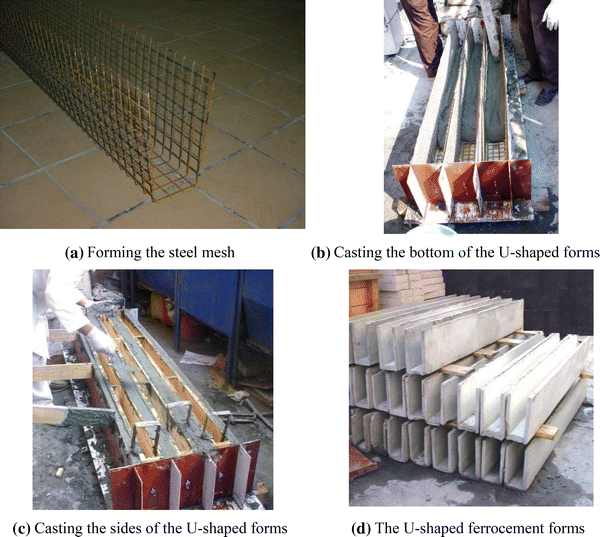
Preparation and casting of the U-shaped ferrocement forms.
-
2.
Wooden pans were placed on top of the cast reinforced mortar layer and the sides of the forms were cast around the wooden pans in each vent of the steel mold as shown in Fig. 4c.
-
3.
The reinforced mortar forms were left for 24 h in the mold before disassembling the mold. At the end of this step, three U-shaped reinforced mortar forms are produced. The forms were covered with wet burlap for 28 days and then were stored as shown in Fig. 4d.

The prepared reinforced mortar U-shaped forms were used as permanent forms to cast the concrete and recycled concrete core of the test specimens. For the beams without mechanical shear connection, the inside surface of the sides and bottom of the U-shaped form was coated with the epoxy bonding agent and the two steel bars of 12 mm diameter were placed inside the U-shaped forms before casting the concrete core. The beams were covered with wet burlap for 28 days before testing.
For the beams with mechanical shear connection, groups 5 and 10, 14 holes were drilled in the U-shaped form; 4 at each side and 6 at the bottom. Fourteen high tensile strength steel bolts were fixed using nuts as shown in Fig. 5 before casting the core. The number of shear connectors on each side of the beam centerline (two on the side and three on the bottom of the U-shaped form) was calculated to transmit the developed ultimate tensile force in the pertinent reinforced mortar layer to the core material through single shearing mechanism in the bolts. The needed number of bolts was two on each side. However, one additional bolt was added at the bottom of the beam on each side to assure full connection and to reduce the spacing between bolts. The head of the bolts protruded outside the U-shaped forms. However, in practice a recess could be provided in the forms to accommodate the bolt head and eliminate such protrusion. For these two groups, the inside surface of the U-shaped form was not coated with bonding agent.

Attaching the mechanical shear connectors to the precast ferrocement forms.
For groups 4 and 9, the inside three surfaces of the U-shaped form were coated using bond enhancing agent. Two high tensile strength steel bars of 12 mm diameter were placed inside the U-shaped forms and a mortar layer of 25 mm thickness was laid around the bars. Lightweight brick units of dimensions 600 × 200 × 70 mm were laid inside the forms on top of the bottom mortar layer and mortar was then cast around and on top of the brick. Based on the inside dimensions of the U-shaped forms and the dimensions of the brick units, the brick core inside the U-shaped form was covered with a mortar of 50 mm thick at the top as shown in Fig. 1c. The beams were covered with wet burlap for 28 days before testing.
The same steel mold, which was used to cast the U-shaped forms, was used to cast the three control specimens. In this case, the three wooden pans were not used. A reinforcing steel cage consisting of two top and two bottom steel bars and five stirrups per meter was prepared for each control specimen. The three steel cages were placed in the vents of the steel mold before casting the concrete. The beams were left in the mold for 48 h before disassembling of the mold and were then covered with wet burlap for 28 days before testing.
2.3 Test Setup
At the time of testing, the specimen was painted with white paint to facilitate the visual crack detection during testing process. A set of eight “demec” points was placed on one side of the specimen to allow measuring the strain versus load during the test. Demec points were centered on the centerline of the specimens as shown in the Fig. 6.

Locations of the demec points.
The specimen was laid on a universal testing machine of maximum capacity of 250 KN, where the test was conducted under a three-point load system with a span of 1,800 mm. A dial gauge with an accuracy of 0.01 mm was placed under the specimen at the center to measure the deflection versus load. Load was applied at 5 kN increments on the specimen exactly at the center. The horizontal distance between each pair of demec points was recorded by using a mechanical strain gauge reader. Concurrently, the beam deflection was determined by recording the dial gauge reading at each load increment. Cracks were traced throughout the sides of the specimen and then marked with red and black markers. The first cracking load of each specimen was recorded. The load was increased until complete failure of the specimen was reached.
3 Theoretical Investigation
3.1 Theoretical Calculation of the First Cracking Load
The first cracking load for the different test specimens was calculated by applying similar method as that used for reinforced concrete section. This method was previously used by Abdel Tawab (2006) and proved to be valid for predicting the first cracking load for the beams incorporating precast permanent reinforced mortar forms. The cracking moment (M cr ) and the cracking load (P cr ) are given by:
where f ctr is the cracking strength of the material, I g is the gross moment of inertia of the section, L is the span of the beam, and y b is the distance from the neutral axis to the bottom of the section. The Egyptian code for reinforced concrete structures (HBRC 2008) defines the tensile strength of the concrete and the form’s mortar (f t ) in terms of the material compressive strength (f cu ) as:
For the concrete, the cracking strength (f ctr.c ) equals f t.c . For the reinforced mortar forms reinforced with expanded steel mesh, the cracking strength of the mortar-reinforcement composite (f ctr.f ) is determined by using the “rule of mixtures” suggested by Rajagopalan and Parameswaran (1975) as:
where V f is the volume fraction of the steel mesh and F ym is the yield or proof stress of the mesh material. For the case of reinforced mortar forms reinforced with welded wire mesh, f ctr.f was found to be more appropriately estimated from the theoretical model proposed by Paramasivam and Nathan (1984) as:
3.2 Theoretical Calculation of Ultimate Flexural Load
The theoretical method used in this research to compute the ultimate load for the test specimens is similar to that presented by Abdel Tawab (2006). The basic assumptions in the calculation of the ultimate moment are:
-
The strains in the mortar matrix, concrete core, and the reinforcing steel are directly proportional to the distances from the neutral axis as shown in Fig. 7.
Fig. 7 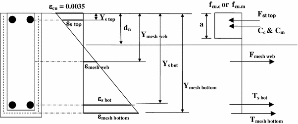
Theoretical strain and Stress distribution and internal forces on the cross section.
-
Failure occurs when the maximum compressive strain in the form’s mortar matrix and the concrete core reaches 0.0035.
-
At ultimate load, the tensile contribution of mortar matrix and the concrete core are neglected and the compressive contribution is represented by a rectangular stress block of depth (a) equals to 0.8d n and stress of 0.67 f cu (HBRC 2008).

The internal forces in the reinforced mortar, concrete core, reinforcing bars, and reinforcing steel meshes are shown in Fig. 7. For equilibrium:
The internal forces C c , C m , F s.top , F mesh.web , T s.bot , and T mesh.bot are shown in Fig. 7 and are given by:
The strain at the top steel bars, bottom steel bars, web steel meshes, and bottom steel meshes could be obtained from the geometry of the strain distribution shown in Fig. 7. σ s.top and ε mesh.web could be tension (positive sign) or compression (negative sign) depending on the location of the neutral axis. The location of the neutral axis (X) is determined by applying trial and error method until Eq. (6) is satisfied. The calculation was performed on the computer using the Microsoft EXCEL sheet. Once the location of the neutral axis is determined and the internal forces are determined, the ultimate moment on the section (M u ) can be calculated by taking the moment about the point of application of the compression force as follows:
Accordingly, for simply supported beam subjected to central concentrated load, the ultimate load (P u1 ) is obtained from the following formula:
For shear failure of the specimen, the ultimate shear strength (Q u ) of the different specimens was considered in the present investigation as:
For the case of specimens with light brick core, the shear strength of the light brick was neglected since it is very small and the beam is considered for this case as a reinforced mortar beam of thickness (B) equal to (2 t).
The shear strength of ferrocement beams was investigated and reported in the literature by some researchers (Mansur and Ong 1991; Desayi and Nandakumar 1995) The adopted method for shear strength calculation in the present analysis is based on the Egyptian Code provision (HBRC 2008) as stated in Eq. (21). The contribution of the web mesh reinforcement, if exists, has also been added to the Egyptian code equation as a replacement to the effect of the stirrups.
The failure load and mode of failure of the beam is determined by the smaller of P u1 and P u2 . If P u1 is the smaller of the two values, the failure mode is “flexural failure”. On the other hand, if P u2 is the smaller value, the failure mode is “shear failure”.
4 Results and Discussion
The test results are listed in Tables 2 and 3 and the load-deflection curves of the test specimens are shown in Figs. 8 and 9. Service load, or flexural serviceability load, given in Tables 2 and 3 is defined as the load corresponding to a deflection equal to span/350 which is the allowed deflection according to the Egyptian code for concrete structures (HBRC 2008). The energy absorption is defined as the area under the load-deflection curve. The theoretical results of the cracking moment and the ultimate load as well as comparison with the experimental results are given in Table 4.

Load-deflection curves for test beams reinforced with welded wire mesh.

Load-deflection curves for test beams reinforced with X8 expanded steel mesh.
Generally, the beams incorporating precast permanent reinforced mortar forms filled with concrete or recycled concrete core achieved better results compared to those of the control specimens as shown in Tables 2 and 3. The percentage of increase in a specific mechanical property varied with the variation of the properties of these beams. The performance of the beams filled with lightweight brick core relative to that of the control beams varied with the type of reinforcing steel mesh.
It is worth noting that the beams incorporating reinforced mortar forms had almost the same stiffness as the control beam upto its cracking load after which they were much stiffer than the control beam. This could be attributed to the fact that these specimens attained the first cracking load at higher level than the control beam and to the role of the reinforcing steel mesh in controlling the crack distribution, height and width.
4.1 Cracking Behavior and Mode of Failure
Figure 10 shows the cracking patterns of the different test groups. For the control specimens, cracking started at mid-span. As the applied load increased, the developed cracks propagated rapidly from the tension side towards the compression side and new cracks developed on each side of the beam centerline. The control beams failed in flexural mode due to crushing of the concrete compression zone at mid span. Spalling of the concrete cover was observed at failure.

Cracking patterns of the test beams.
For the beams incorporating precast reinforced mortar forms and concrete core or recycled concrete core, the cracking patterns were similar to those of the control beams. However, the first crack was observed at higher load compared to that of the control beams and at failure the observed crack widths were less than those of the control beams. This better cracking behavior is attributed to the presence of the steel mesh in the sides of the U-shaped forms. The number and width of the developed cracks varied with the variation of the type and number of the steel meshes. The mode of failure of these groups of beams was also flexural, similar to the control beams, due to crushing of the concrete compression zone. Spalling of the concrete cover was observed at failure for some of the beams.
Cracking patterns for the beams with lightweight brick core varied with the type of steel mesh. For the welded wire mesh (WSB1, WSB2, and WSB3) the cracks were almost vertical and spread along the whole length of the beam as shown in Fig. 10. For the case of X8 steel mesh (ESB1, ESB2, and ESB3) diagonal cracks were developed close to the supports at later stage of loading. The crack propagation along the beam depth for the beams with welded wire meshes was less than that for the beams with X8 expanded steel mesh. Before failure of beams reinforced with welded wire mesh (WSB1, WSB2, and WSB3), separation of the side of the U-shaped form the brick core was observed as shown in Fig. 11 and the beams then failed in flexural mode due to crushing of the concrete compression zone at mid span. Beams ESB1, ESB2, and ESB3 failed in shear mode. Although the shear span/depth ratio for ESB specimen is more than 2.5 which indicates that for a typical reinforced concrete beam it would fail in flexural mode, the provided shear strength by the web reinforcement together with the weak brick core was not enough to reach the flexural capacity of the specimen.

Separation of the side of the ferrocement form from the brick core for beams of group 4.
4.2 Effects of the Test Parameters on the Mechanical Properties of the Test Beams
The effects of the test parameters on the mechanical properties of the proposed beams in terms of deflection characteristics, first cracking load, service load, ultimate load, mode of failure, and energy absorption are presented in the following sections.
4.2.1 Effect of the Type and Number of Layers of the Steel Mesh
The beams reinforced with welded wire mesh achieved better cracking performance than those reinforced with X8 expanded steel mesh regardless of the number of reinforcing steel layers and the type of core material. From the results in Tables 2 and 3, the ratio of the first cracking load of the welded wire mesh beams to that of the X8 expanded steel mesh beams was 1.12, 1.33, 1.4, 1.2, 1.19 for (WSC/ESC), (WDC/EDC), (WSB/ESB), (WSS/ESS), and (WSR/ESR) respectively. The better performance of the beams reinforced with welded wire mesh could be attributed to the material properties of the two types of steel meshes which resulted in higher tensile strength of the mortar-mesh composite for the case of welded wire mesh in comparison to that of the X8 expanded steel mesh as explained in Eqs. (4) and (5).
The serviceability load showed minor change with the type and number of reinforcing mesh which indicates minor effect on the stiffness of the beams. The theoretical calculation showed that the type of the steel mesh had minor effect on the moment of inertia and consequently the stiffness of the beams. The change in the stiffness beyond the first crack and upto failure could be attributed to the difference in the value of the first cracking load and the role of each type of steel mesh in controlling the crack height and width.
Although both types of steel meshes had almost the same total volume fraction V r , the difference in the efficiency factor for both types resulted in a higher longitudinal volume fraction V rl for the case of X8 expanded steel mesh as shown in Table 1. However, the results show that the welded wire mesh achieved higher ultimate load in comparison to those of the X8 expanded steel mesh. Comparing the results of specimens (WSC) with (ESC), (WSS) with (ESS), and (WSR) with (ESR) shows that the ultimate load was higher by 18, 12, and 19 % respectively. This could be attributed to the higher ultimate strength of the welded wire mesh in comparison to that of the X8 expanded steel mesh as mentioned in Sect. 2.1. The slight variation in the percentage of increase in the ultimate load could be attributed to the slight difference in the ultimate strength of the concrete and mortar of the different beams. For the case of double reinforcing layers, the ultimate load of specimen (WDC) was higher than that of (EDC) by about 35 %. The ultimate load of specimen (WSB) was higher than that of (ESB) by about 88 %. This large percentage of increase in the ultimate load for this type of core material is due to the fact that specimen (ESB) failed due shear as X8 expanded steel mesh was insufficient for providing the shear strength together with the weak lightweight brick while specimen (WSB) reached its ultimate flexural strength.
All specimens with solid concrete or recycled concrete core achieved higher energy absorption than that of the control beam as shown in Table 5. The energy absorption of specimens (WSC), (WSS), and (WSR) was higher than that of specimens (ESC), (ESS), and (ESR) by about 14 %. Specimen (WDC) showed much higher energy absorption than that of specimen (EDC) by about 51 %. The comparison between the performance of specimen (WSB) and (ESB) was influenced by the early failure of specimen (ESB) due to shear. The ratio of the energy absorption of specimen (WSB) to that of (ESB) was about 1.88. It is worth noting that specimens (WSB) and (ESB) reached about 41 % and 22 % of the energy absorption of the control beams respectively.
4.2.2 Effect of the Core Material
The effect of the type of solid core material is studied by comparing the results of specimens (WSC) and (WSR) and the results of specimens (ESC) and (ESR). In summary, the type of solid core material has minor effect on the beam initial stiffness, first cracking load, serviceability load, ultimate load, and energy absorption.
Close look at Figs. 8 and 9 shows that specimens (WSC) and (WSR) have almost the same stiffness upto a load of about 60 kN. Beyond this load, minor difference in the stiffness is observed upto the ultimate load. The two specimens showed a difference of 0 % in the first cracking load, 0.4 % in the serviceability load, 2.4 % in the ultimate load, and 2.0 % in the energy absorption. The two specimens reached deflection of 20.4 and 20.0 mm at ultimate. The same behavior was also observed for specimens (ESC) and (ESR) where the stiffness of the beams was almost the same upto load of about 55 kN. These two specimens had difference of 6.0 % in the first cracking load, 0 % in the serviceability load, 1.3 % in the ultimate load, and 2.6 % in the energy absorption. The two specimens reached deflection of 20.1 and 19.6 mm at ultimate load. The slight difference in the mechanical properties of the beams under investigation could be attributed to the slight difference in the tensile and compressive strength of the form’s mortar and core material.
On the other hand, the lightweight brick core resulted in substantial reduction in the stiffness of the beam, first cracking load, serviceability load, ultimate load and energy absorption in comparison to the beams incorporation solid concrete/recycled concrete core. It is worth noting that the specimens incorporating welded wire mesh and lightweight brick core reached 107 % of the ultimate load of the control specimen even though failure of this specimen occurred due separation of the sides of the U-shaped forms before reaching the flexural strength of the beam as shown in Fig. 11. The beams with X8 expanded steel mesh and lightweight brick core failed in shear at 82.4 % of the ultimate load of the control beam.
4.2.3 Effect of the Type of Shear Connection
Comparing the results of specimen (WSS) with mechanical shear connection with the results of specimen (WSC) with the epoxy bonding agent shows no/minor change in the first cracking load (0 %), serviceability load (0 %), ultimate load (2.3 %), and energy absorption (2.1 %). Similar results are obtained when the results of specimens (ESS) and (ESC) were compared where the calculated differences were (6.0 %) in the first cracking load, (0 %) in the serviceability load, (2.6 %) in the ultimate load, and (2.5 %) in the energy absorption. Figures 8 and 9 show that the load-deflection curves for these two types of shear connection were almost identical. These results indicate that the epoxy bonding agent was sufficient to provide the interaction between the precast U-shaped forms and the filling concrete core. The beams with lightweight brick core were constructed using the epoxy bonding agent only to provide shear connection between the precast skin and the core. Accordingly, the investigation of the effect of the type of shear connection for this case was outside the scope of the present research. This could be investigated in future research.
4.3 Comparison Between the Theoretical and Experimental Results
The geometric and material properties of the test specimens were used to calculate the respective first crack and ultimate load for each specimen. The theoretical results together with a comparison with the experimental results are shown in Table 4. The table shows that the predicted results of the first cracking load are very close to the experimental ones for all test specimens. The ratio of the experimental first cracking loads to the predicted ones ranged from 0.91 to 1.08.
The predicted ultimate loads are in good agreement with the experimental observations for all specimens except specimen (WSB). It should be noted here that failure of this specimen occurred due to separation of the sides of the reinforced mortar forms before reaching the flexural strength of the beam as shown in Fig. 11. The theoretical model was not formulated to detect such mode of failure. The ratio of the experimental ultimate loads to the theoretical ones ranged from 0.99 to 1.09.
The predicted modes of failure agreed with the observed experimental ones for all test specimens.
5 Conclusions
Within the scope and parameters considered in present research and based on the test results and observations of the experimental investigation; the following conclusions may be drawn:
-
1.
The beams incorporating permanent reinforced mortar forms filled with concrete or recycled concrete core achieved higher first cracking load, serviceability load, ultimate load, and energy absorption compared to the control specimen irrespective of the type and number of layers of the steel mesh.
-
2.
Using recycled concrete as a core material did not have significant drawbacks on the beam’s mechanical behavior.
-
3.
The beams incorporating lightweight brick core achieved higher first cracking load and ultimate load relative to the conventional concrete beams when welded wire mesh was employed. On the other hand, there is no change in the first cracking load and reduction in the ultimate load was achieved when expanded wire mesh was used. Using lightweight brick core resulted in a decrease in the serviceability load and energy absorption relative to the conventional concrete beams regardless of the type of steel mesh used.
-
4.
Within the range of test parameter, the U-shaped steel mesh in the permanent reinforced mortar forms provided sufficient shear reinforcement for the beams under investigation except for the beams with lightweight brick core and expanded steel mesh reinforcement.
-
5.
Use of bond enhancing coating between the precast reinforced mortar forms and the core material provides sufficient shear connection between the two surfaces, the use of mechanical shear connector resulted in an insignificant change in the beam’s mechanical properties in comparison with those with bond enhancing coating.
-
6.
The beams incorporating thin precast reinforced mortar U-shaped forms could be successfully used as an alternative to the traditional reinforced concrete beams, which could be of true merit in both developed and developing countries besides its anticipated economic and environmental merits. Further research needs to be conducted to reach sound recommendations for practical use especially for the beams with light brick core.
- A s.bot :
-
Area of the steel bars at bottom of the beam
- A s.top :
-
Area of the steel bars at top of the beam (if they exist)
- A mesh.bot :
-
Area of the steel meshes in the mortar layer under the core
- A mesh.web :
-
Area of the steel meshes in the mortar layer on each side of the beam
- A mesh.web.y :
-
The cross sectional area of the web mesh reinforcement in the vertical direction within a length equal to (d)
- a :
-
Depth of the compression block
- B :
-
Total width of the beam
- C c :
-
The compressive force on the concrete block
- C m :
-
The compressive force on the mortar of the mortart skin
- d :
-
The effective depth of the beam
- d n :
-
Neutral axis depth from the top of the specimen
- E s :
-
Modulus of elasticity of the steel
- F mesh.web :
-
The force on the mesh reinforcement in the two faces of the beam which could be positive or negative depending on the location of the neutral axis
- F s.top :
-
The force on the top reinforcement which could be positive or negative depending on the location of the neutral axis
- F ys , F ym :
-
Yield stress or proof stress of the reinforcing steel bars and steel mesh
- F u :
-
Ultimate strength of the steel bars
- f cu.c , f cu.m :
-
Compressive strength of the concrete and mortar
- I g :
-
Moment of inertia of the composite section about its neutral axis
- L :
-
Span of the specimen
- M cr :
-
Moment at the first crack
- M u :
-
Ultimate moment of the beam
- P u1 :
-
Ultimate load for flexural failure
- P u2 :
-
Ultimate load for shear failure
- T mesh.bot :
-
The tensile force on the steel mesh at the bottom of the beam
- T s.bot :
-
The tension force on the bottom steel
- t :
-
Thickness of the mortar layer
- V f :
-
Volume fraction of the reinforcing steel mesh
- y b :
-
Distance from the neutral axis to the bottom of the specimen
- y s.bot :
-
Distance between the bottom steel bars and the compressive force (Cc)
- y s.top :
-
Distance between the top steel bars and the compressive force (Cc)
- y mesh.web :
-
Distance between the center of the web steel mesh and the compressive force (Cc)
- y mesh.bot :
-
Distance between the bottom steel meshes and the compressive force (Cc)
- E sth :
-
Strain-hardening modulus of the steel
- ε ys :
-
Yield strain of the reinforcing steel bars
- ε mesh.web , σ mesh.web :
-
Strain and stress at the level of mesh reinforcement at the sides of the beam
- ε mesh.bot , σ mesh.bot :
-
Strain and stress at the level of mesh reinforcement at the bottom of the beam
- ε s.bot, σ s.bot :
-
Strain and stress at the level of bottom steel bars
- ε s.top, σ s.top :
-
Strain and stress at the level of top steel bars
References
Abdel Tawab Alaa. (2006). Development of permanent formwork for beams using ferrocement laminates, P.H.D. Thesis submitted to Menoufia University, Egypt.
Al-Rifaei, W. N., & Hassan, A. H. (1994). Structural behavior of thin ferrocement one-way bending elements. Journal of Ferrocement,24(2), 115–126.
American Concrete Institute, ACI Committee 549-1R-88. (2006). Guide for the design, construction, and repair of ferrocement. manual of concrete practice (p. 30). Framington Hill: American Concrete Institute, ACI Committee 549-1R-88.
ASTM Committee C09 on Concrete and Concrete aggregate (2012). Standard Specification for Epoxy-Resin-Base Bonding Systems for Concrete, ASTM International, 100 Barr Harbor Drive, PO Box C700, West Conshohocken, PA 19428-2959, US, 12p.
Chandrasekhar Rao, T., Gunneswara Rao, T. D., & Ramana Rao, N. V. (2008). An experimental study on ferro cement channel units under flexural loading. International Journal of Mechanics and Solids,3(2), 195–203.
Desayi, P., & Nandakumar, N. (1995). A semi-empirical approach to predict shear strength of ferrocement. Cement and Concrete Composites,17(3), 207–218.
Fahmy, E. H., Shaheen, Y. B. I., Abou Zeid, M. N., & Gaafar, H. M. (2006). Ferrocement sandwich and hollow core panels for wall construction. Journal of Ferrocement,36(3), 876–891.
Fahmy, E. H., Shaheen, Y. B. I., Abou Zeid, M. N., & Gaafar, H. M. (2012). Ferrocement sandwich and hollow core panels for floor construction. Canadian Journal of Civil Engineering,39(12), 1297–1310.
Fahmy, E. H., Shaheen, Y. B. I., & Korany, Y. S. (1997a). Repairing reinforced concrete beams by ferrocement. Journal of Ferrocement,27((1), 19–32.
Fahmy, E. H., Shaheen, Y. B. I., & Korany, Y. S. (1997b). Use of ferrocement laminates for repairing reinforced concrete slabs. Journal of Ferrocement,27(3), 219–232.
Fahmy, E. H., Shaheen, Y. B. I., & Korany, Y. S. (1999). Repairing reinforced concrete columns using ferrocement laminates. Journal of Ferrocement,29(2), 115–1124.
Gregson S., & Dickson M. (1994). Schlumberger Cambridge Phase 2: Design and Construction of First Floor Slab Using Ferrocement Soffit Units, Ferrocement. In P. J. Nedwell, & R. N. Swamy (Eds.), Proceedings of the Fifth International Symposium, (pp. 227–239) New York, NY: Taylor and Francis.
Housing and Building Research Center (HBRC). (2008). The Egyptian code for design and construction of concrete structures. Cairo, Egypt: Housing and Building Research Center (HBRC).
International Ferrocement Society (IFS), IFS Committee 10. (2001). Ferrocement Model Code, Asian Institute of Technology, International Ferrocement Information Center, Thailand.
Karlsson, M. (1997). Recycling of concrete (p. 58). Goteborg, Sweden: Chalmers University of Technology.
Korany Y. S. (1996). Repairing reinforced concrete columns using ferrocement laminates, MS Thesis submitted to The American University in Cairo, Egypt, 151p.
Mansur, M. A., & Ong, K. C. G. (1991). Behaviour of reinforced fibre concrete deep beams in shear”. ACI Structural Journal,88, 98–105.
Mays, G. C., & Barnes, R. A. (1995). Ferrocement permanent formwork as protection to reinforced concrete. Journal of Ferrocement,25(4), 331–345.
Naaman, A. E. (1979). Performance criteria for ferrocement. Journal of Ferrocement,9(2), 75–91.
Naaman, A. E. (2000). Ferrocement and Laminated Cementitious Composites. MI: Techno Press.
National Academy of Sciences. (1973). Ferrocement: applications in developing countries. A report of an adhoc panel of the advisory committee on technological innovation board on science and technology for international development office of the foreign secretary, Washington, DC.
Paramasivam, P., & Nathan, G. K. (1984). Prefabricated ferrocement water tanks. Journal of the American Concrete Institute,81(6), 580–586.
Rajagopalan, K., & Parameswaran, V. S. (1975). Analysis of ferrocement beams. Journal of Structural Engineering,2(04), 155–164.
Abdel Tawab, A., Fahmy, E. H., & Shaheen, Y. B. (2012). Use of permanent ferrocement forms for concrete beam construction. Materials and Structures,45(9), 1319–1329.
Singh G., Venn A. B., & Xiong, G. J. (1994). An Innovative Use of Ferrocement, Ferrocement. In P. J. Nedwell, & R. N. Swamy (Eds.), Proceedings of the Fifth International Symposium (pp. 219–226) New York, NY: Taylor and Francis.
Yogendran, V., Langan, B. W., Haque, M. N., & Ward, M. A. (1987). Silica fume in high strength concrete. ACI Materials Journal,87(51), 124–129.
Author information
Authors and Affiliations
Corresponding author
Rights and permissions
This article is published under license to BioMed Central Ltd. Open Access This article is distributed under the terms of the Creative Commons Attribution License which permits any use, distribution, and reproduction in any medium, provided the original author(s) and the source are credited.
About this article
Cite this article
Fahmy, E.H., Shaheen, Y.B.I., Abdelnaby, A.M. et al. Applying the Ferrocement Concept in Construction of Concrete Beams Incorporating Reinforced Mortar Permanent Forms. Int J Concr Struct Mater 8, 83–97 (2014). https://doi.org/10.1007/s40069-013-0062-z
Received:
Accepted:
Published:
Issue Date:
DOI: https://doi.org/10.1007/s40069-013-0062-z